Chapter: Electrical machines : Three Phase Induction Motor
Phasor Diagram of Three Phase Induction Motor
Phasor Diagram of Three Phase
Induction Motor
In a
3-phase induction motor, the stator winding is connected to 3-phase supply and
the rotor winding is short-circuited. The energy is transferred magnetically
from the stator winding to the short-circuited, rotor winding. Therefore, an
induction motor may be considered to be a transformer with a rotating secondary
(short-circuited). The stator winding corresponds to transformer primary and
the rotor finding corresponds to transformer secondary. In view of the
similarity of the flux and voltage conditions to those in a transformer, one
can expect that the equivalent circuit of an induction motor will be similar to
that of a transformer. Fig. 3.8 shows the equivalent circuit per phase for an
induction motor. Let discuss the stator and rotor circuits separately.
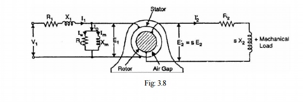
Stator circuit. In the stator, the events are
very similar to those in the transformer primary. The applied voltage per phase to the stator is V1 and R1and X1 are the
stator resistance and leakage reactance per phase respectively. The applied
voltage V1 produces a magnetic flux which links the stator winding (i.e.,
primary) as well as the rotor winding (i.e., secondary). As a result,
self-induced e.m.f. E1 is induced in the stator winding and mutually induced
e.m.f.
E'2 (= s E2
= s K E2 where K is transformation ratio) is induced in the rotor winding. The
flow of stator current I1 causes voltage drops in R1 and
X1.
V1 = - E1 + I1(R1+jX1) …… phasor sum
When the
motor is at no-load, the stator winding draws a current I0. It has two
components viz.,
(i) which
supplies the no-load motor losses and (ii) magnetizing component Im which sets
up magnetic flux in the core and the air gap. The parallel combination of Rc
and Xm, therefore, represents the no-load motor losses and the production of
magnetic flux respectively.
I0
= Iw + Im
Rotor circuit. Here R2 and X2 represent the
rotor resistance and standstill rotor reactance per phase respectively. At any slip s, the rotor reactance will be X2
.The induced voltage/phase in the rotor is E'2 = s E2 = s K E1 . Since the rotor winding is
short-circuited, the whole of e.m.f. E'2 is used up in circulating
the rotor current I'2.
E’2
= I’2 (R2 + jsX2)
The rotor
current I'2 is reflected as I"2 (= K I'2) in the
stator. The phasor sum of I"2 and I0 gives the
stator current I1.
It is
important to note that input to the primary and output from the secondary of a
transformer are electrical. However, in an induction motor, the inputs to the
stator and rotor are electrical but the output from the rotor is mechanical. To
facilitate calculations, it is desirable and necessary to replace the
mechanical load by an equivalent electrical load. We then have the transformer
equivalent circuit of the induction motor.
It may be
noted that even though the frequencies of stator and rotor currents are
different, yet the magnetic fields due to them rotate at synchronous speed Ns.
The stator currents produce a magnetic flux which rotates at a speed Ns. At
slip s, the speed of rotation of the rotor field relative to the rotor surface
in the direction of rotation of the rotor is

But the
rotor is revolving at a speed of N relative to the stator core. Therefore, the
speed of rotor field relative to stator core

Thus no
matter what the value of slip s, the stator and rotor magnetic fields are
synchronous with each other when seen by an observer stationed in space.
Consequently, the 3-phase induction motor can be regarded as being equivalent
to a transformer having an air-gap separating the iron portions of the magnetic
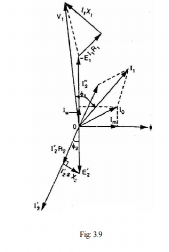
circuit carrying the primary and secondary windings. Fig. 3.9 shows the
phasordiagram of induction motor.
Related Topics