Chapter: Electrical machines : Three Phase Induction Motor
Performance Characteristics of Three phase Induction Motor
Performance Characteristics of Three phase Induction Motor
The equivalent circuits derived in the preceding section can be used to predict the performance characteristics of the induction machine. The important performance characteristics in the steady state are the efficiency, power factor, current, starting torque, maximum (or pull-out) torque.
1. The complete torque-speed characteristic
In order to estimate the speed torque characteristic let us suppose that a sinusoidal voltage is impressed on the machine. Recalling that the equivalent circuit is the per-phase representation of the machine, the current drawn by the circuit is given by
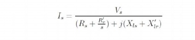
Where, Vs is the phase voltage phasor and Isis the current phasor. The magnetizing current is neglected. Since this current is flowing through R′r/s, the air-gap power is given by
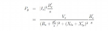
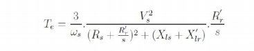
The mechanical power output was shown to be (1-s)Pg (power dissipated in R′r/s). The torque is obtained by dividing this by the shaft speed ωm .Thus we have,

Where ωm is the synchronous speed in radians per second and s is the slip. Further, this is the torque produced per phase. Hence the overall torque is given by
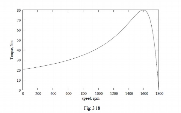
The torque may be plotted as a function of 's' and is called the torque-slip (or torque- speed, since slip indicates speed) characteristic a very important characteristic of the induction machine.
A typical torque-speed characteristic is shown in Fig: 3.18. This plot corresponds to a 3 kW, 4 pole, and 60 Hz machine. The rated operating speed is 1780 rpm.
Further, this curve is obtained by varying slip with the applied voltage being held constant. Coupled with the fact that this is an equivalent circuit valid under steady state, it implies that if this characteristic is to be measured experimentally, we need to look at the torque for a given speed after all transients have died down. One cannot, for example, try to obtain this curve by directly starting the motor with full voltage applied to the terminals and measuring the torque and speed dynamically as it runs up to steady speed.
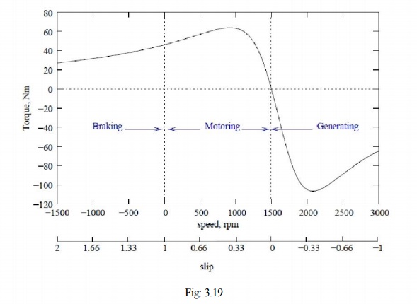
With respect to the direction of rotation of the air-gap flux, the rotor maybe driven to higher speeds by a prime mover or may also be rotated in the reverse direction. The torque-speed relation for the machine under the entire speed range is called the complete speed-torque characteristic. A typical curve is shown in Fig: 3.19 for a four-pole machine, the synchronous speed being 1500 rpm. Note that negative speeds correspond to slip values greater than 1, and speeds greater than 1500 rpm correspond to negative slip. The plot also shows the operating modes of the induction machine in various regions. The slip axis is also shown for convenience.
2. Effect of Rotor Resistance on Speed Torque Characteristic
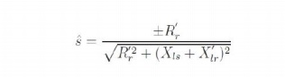
Restricting ourselves to positive values of slip, we see that the curve has a peak point. This is the maximum torque that the machine can produce, and is called as stalling torque. If the load torque is more than this value, the machine stops rotating or stalls. It occurs at a slip ˆs, which for the machine of Fig: 3.19 is 0.38. At values of slip lower than ˆs, the curve falls steeply down to zero at s = 0. The torque at synchronous speed is therefore zero. At values of slip higher than s = ˆs, the curve falls slowly to a minimum value at s = 1. The torque at s = 1 (speed = 0) is called the starting torque. The value of the stalling torque may be obtained by differentiating the expression for torque with respect to zero and setting it to zero to find the value of ˆs. Using this method, we can write
Substituting ˆs into the expression for torque gives us the value of the stalling torque ˆ Te,
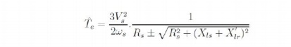
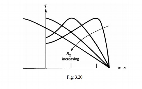
The expression shows that ˆ Te is the independent of R′r, while ˆs is directly proportional to R′r. This fact can be made use of conveniently to alter ˆs. If it is possible to change R′r, then we can get a whole series of torque-speed characteristics, the maximum torque remaining constant all the while.
We may note that if R′r is chosen equal to =
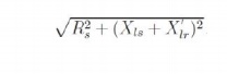
The ˆs, becomes unity, which means that the maximum torque occurs at starting. Thus changing of R′r, wherever possible can serve as a means to control the starting torque Fig: 3.20.
While considering the negative slip range, (generator mode) we note that the maximum torque is higher than in the positive slip region (motoring mode).
3. Operating Point and Stable & Unstable region of Operation
Consider a speed torque characteristic shown in fig. 25 for an induction machine, having the load characteristic also superimposed on it. The load is a constant torque load i.e. the torque required for operation is fixed irrespective of speed.
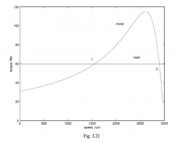
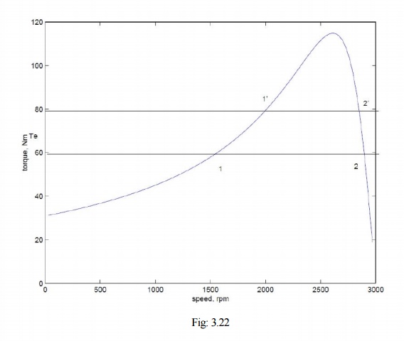
The system consisting of the motor and load will operate at a point where the two characteristics meet. From the above plot, we note that there are two such points. We therefore need to find out which of these is the actual operating point. To answer this we must note that, in practice, the characteristics are never fixed; they change slightly with time. It would be appropriate to consider a small band around the curve drawn where the actual points of the characteristic will lie. This being the case let us considers that the system is operating at point 1, and the load torque demand increases slightly. This is shown in Fig: 3.22, where the change is exaggerated for clarity. This would shift the point of operation to a point 1′ at which the slip would be less and the developed torque higher.
The difference in torque developed △Te, being positive will accelerate the machine. Any overshootin speed as it approaches the point 1′ will cause it to further accelerate since the developed torque is increasing. Similar arguments may be used to show that if for some reason the developed torque The difference in torque developed △Te, being positive will accelerate the machine. Any overshoot becomes smaller the speed would drop and the effect is cumulative. Therefore we may conclude that 1 is not a stable operating point.
Let us consider the point 2. If this point shifts to 2′, the slip is now higher (speed is lower) and the positive difference in torque will accelerate the machine. This behaviour will tend to bring the operating point towards 2 once again. In other words, disturbances at point 2 will not cause a runaway effect. Similar arguments may be given for the case where the load characteristic shifts down. Therefore we conclude that point 2 is a stable operating point.
From the above discussions, we can say that the entire region of the speed-torque characteristic from s = 0 to s = ˆs is an unstable region, while the region from s = ˆs to s = 0 is a stable region. Therefore the machine will always operate between s = 0 and s = ˆs.
Related Topics