Chapter: Electrical machines : Three Phase Induction Motor
Circle Diagram - analyse the three phase induction motor performance
Circle Diagram
To analyse the three phase induction motor performance using circle diagram we need to determine the equivalent circuit parameters of the machine.
1. Approximate Equivalent Circuit of Induction Motor
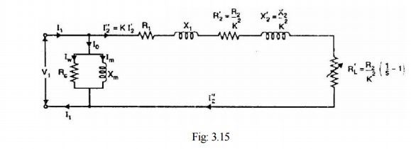
As in case of a transformer, the approximate equivalent circuit of an induction motor is obtained by shifting the shunt branch (Rc - Xm) to the input terminals as shown in Fig. 3.15. This step has been taken on the assumption that voltage drop in R1 and X1 is small and the terminal voltage V1 does not appreciably differ from the induced voltage E1. Fig. 3.15 shows the approximate equivalent circuit per phase of an induction motor where all values have been referred to primary (i.e., stator).
The above approximate circuit of induction motor is not so readily justified as with the transformer. This is due to the following reasons:
(i) Unlike that of a power transformer, the magnetic circuit of the induction motor has an air-gap. Therefore, the exciting current of induction motor (30 to 40% of full-load current) is much higher than that of the power transformer. Consequently, the exact equivalent circuit must be used for accurate results.
(ii) The relative values of X1 and X2 in an induction motor are larger than the corresponding ones to be found in the transformer. This fact does not justify the use of approximate equivalent circuit
(iii) In a transformer, the windings are concentrated whereas in an induction motor, the windings are distributed. This affects the transformation ratio.
In spite of the above drawbacks of approximate equivalent circuit, it yields results that are satisfactory for large motors. However, approximate equivalent circuit is not justified for small motors.
2. Tests to Determine the Equivalent Circuit Parameters
In order to find values for the various elements of the equivalent circuit, tests must be conducted on a particular machine, which is to be represented by the equivalent circuit. In order to do this, we note the following.
1. When the machine is run on no-load, there is very little torque developed by it. In an ideal case where there is no mechanical losses, there is no mechanical power developed at no-load. Recalling the explanations in the section on torque production, the flow of current in the rotor is indicative of the torque that is produced. If no torque is produced, one may conclude that no current would be flowing in the rotor either. The rotor branch acts like an open circuit. This conclusion may also be reached by reasoning that when there is no load, an ideal machine will run up to its synchronous speed where the slip is zero resulting in an infinite impedance in the rotor branch.
2. When the machine is prevented from rotation, and supply is given, the slip remains at unity. The elements representing the magnetizing branch Rm&Xm are high impedances much larger than R’r & X’ir in series. Thus, in the exact equivalent circuit of the induction machine, the magnetizing branch may be neglected.
From these considerations, we may reduce the induction machine equivalent circuit of Fig.3.13 &Fig: 3.15 to those shown in Fig: 3.16.
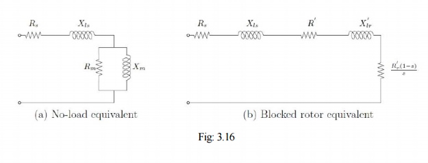
These two observations and the reduced equivalent circuits are used as the basis for the two most commonly used tests to find out the equivalent circuit parameters — the blocked rotor test and no load test. They are also referred to as the short circuit test and open circuit test respectively in conceptual analogy to the transformer.
1. No-load test
The behaviour of the machine may be judged from the equivalent circuit of Fig: 3.16 (a). The current drawn by the machine causes a stator-impedance drop and the balance voltage is applied across the magnetizing branch. However, since the magnetizing branch impedance is large, the current drawn is small and hence the stator impedance drop is small compared to the applied voltage (rated value). This drop and the power dissipated in the stator resistance are therefore neglected and the total power drawn is assumed to be consumed entirely as core loss. This can also be seen from the approximate equivalent circuit, the use of which is justified by the foregoing arguments. This test therefore enables us to compute the resistance and inductance of the magnetizing branch in the following manner.
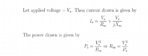
Vs,Is and Ps are measured with appropriate meters. With Rm known by above equation, Xm also can be found. The current drawn is at low power factor and hence a suitable wattmeter should be used.
2. Blocked-rotor Test
In this test the rotor is prevented from rotation by mechanical means and hence the name. Since there is no rotation, slip of operation is unity, s = 1. The equivalent circuit valid under these conditions is shown in Fig: 3.16 (b). Since the current drawn is decided by the resistance and leakage impedances alone, the magnitude can be very high when rated voltage is applied. Therefore in this test, only small voltages are applied — just enough to cause rated current to flow. While the current magnitude depends on the resistance and the reactance, the power drawn depends on the resistances.
The parameters may then be determined as follows. The source current and power drawn may be written as
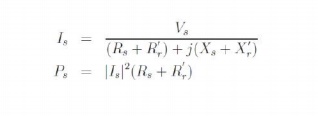
In the test Vs, Is and Ps are measured with appropriate meters. Above equation enables us to compute (Rs + R′r). Once this is known, (Xs + X′r) may be computed from the above equation.
Note that this test only enables us to determine the series combination of the resistance and the reactance only and not the individual values. Generally, the individual values are assumed to be equal; the assumption Rs = R′r, and Xs = X′r suffices for most purposes.
In practice, there are differences. If more accurate estimates are required IEEE guidelines may be followed which depend on the size of the machine.
These two tests determine the equivalent circuit parameters in a 'Stator-referred' sense, i.e., the rotor resistance and leakage inductance are not the actual values but what they 'appear to be' when looked at from the stator. This is sufficient for most purposes as interconnections to the external world are generally done at the stator terminals.
3. Construction of Circle Diagram
Conduct No load test and blocked rotor test on the induction motor and find out the per phase values of no load current I0, short circuit current ISC and the corresponding phase angles Ф0 and ФSC. Also find short circuit current ISN corresponding to normal supply voltage. With this data, the circle diagram can be drawn as follows see Fig: 3.17.
1. With suitable scale, draw vector OA with length corresponding to I0 at an angle Ф0 from the vertical axis. Draw a horizontal line AB.
2. Draw OS equal to ISN at an angle ФSC and join AS.
3. Draw the perpendicular bisector to AS to meet the horizontal line AB at C.
4. With C as centre, draw a portion of circle passing through A and S. This forms the circle diagram which is the locus of the input current.
5. From point S, draw a vertical line SL to meet the line AB.
6. Divide SL at point K so that SK : KL = rotor resistance : stator resistance.
7. For a given operating point P, draw a vertical line PEFGD as shown. then PE = output power, EF = rotor copper loss, FG = stator copper loss, GD = constant loss (iron loss + mechanical loss)
8. To find the operating points corresponding to maximum power and maximum torque, draw tangents to the circle diagram parallel to the output line and torque line respectively. The points at which these tangents touch the circle are respectively the maximum power point and maximum torque point.
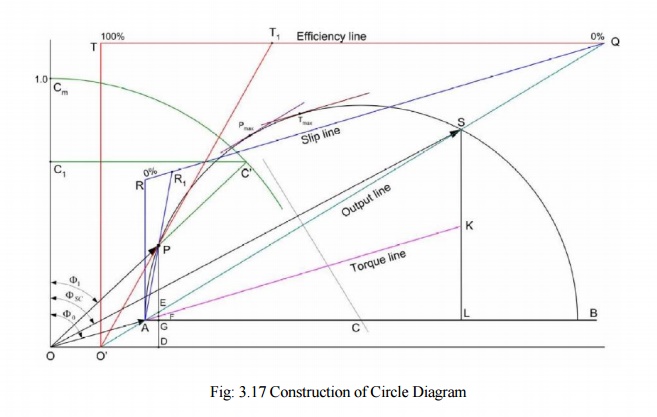
Efficiency line
1. The output line AS is extended backwards to meet the X-axis at O′.
2. From any convenient point on the extended output line, draw a horizontal line QT so as to meet the vertical from O′. Divide the line QT into 100 equal parts.
3. To find the efficiency corresponding to any operating point P, draw a line from O′ to the efficiency line through P to meet the efficiency line at T1. Now QT1 is the efficiency.
Slip Line
1. Draw line QR parallel to the torque line, meeting the vertical through A at R. Divide RQ into 100 equal parts.
2. To find the slip corresponding to any operating point P, draw a line from A to the slip line through P to meet the slip line at R1. Now RR1 is the slip
Power Factor Curve
1. Draw a quadrant of a circle with O as centre and any convenient radius. Divide OCm into 100 equal parts.
2. To find power factor corresponding to P, extend the line OP to meet the power factor curve at C′. Draw a horizontal line C′C1 to meet the vertical axis at C1. Now OC1 represents power factor.
Related Topics