Chapter: Electrical machines : Three Phase Induction Motor
Equivalent Circuit of Three Phase Induction Motor
Equivalent Circuit of Three Phase
Induction Motor
Fig. 3.10
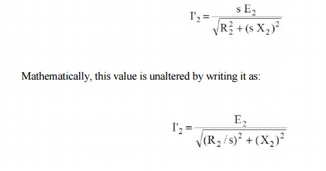
(i) shows the equivalent circuit per phase of the rotor at slip s. The rotor
phase current is given by;
As shown
in Fig. 3.10 (ii), we now have a rotor circuit that has a fixed reactance X2
connected in series with a variable resistance R2/s and supplied with constant
voltage E2. Note that Fig. 3.10 (ii) transfers the variable to the
resistance without altering power or power factor conditions.
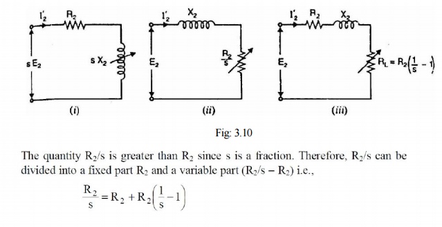
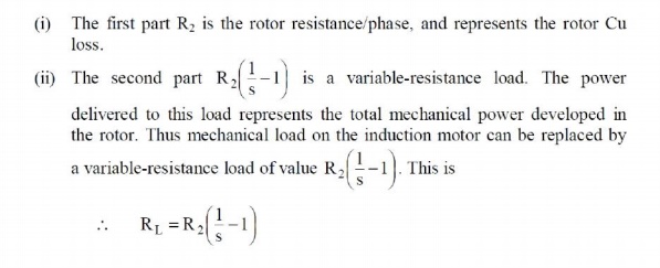
Fig. 3.10
(iii) shows the equivalent rotor circuit along with load resistance RL.
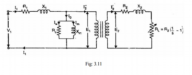
Now Fig:
3.11 shows the equivalent circuit per phase of a 3-phase induction motor. Note
that mechanical load on the motor has been replaced by an equivalent electrical
resistance RL given by;
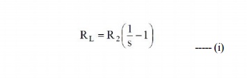
The
circuit shown in Fig. 3.11 is similar to the equivalent circuit of a
transformer with secondary load equal to R2 given by eq. (i). The
rotor e.m.f. in the equivalent circuit now depends only on the transformation
ratio K (= E2/E1).
Therefore;
induction motor can be represented as an equivalent transformer connected to a
variable-resistance load RL given by eq. (i). The power delivered to
RL represents the total mechanical power developed in the rotor.
Since the equivalent circuit of Fig. 3.11 is that of a transformer, the
secondary (i.e., rotor) values can be transferred to primary (i.e., stator)
through the appropriate use of transformation ratio K. Recall that when
shifting resistance/reactance from secondary to primary, it should be divided
by K2 whereas current should be multiplied by K. The equivalent circuit of an
induction motor referred to primary is shown in Fig. 3.12.
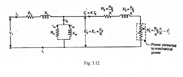
Note that
the element (i.e., R'L) enclosed in the dotted box is the equivalent
electrical resistance related to the mechanical load on the motor. The
following points may be noted from the equivalent circuit of the induction
motor:
(i)
At no-load, the slip is practically zero and the
load R'L is infinite. This condition resembles that in a transformer
whose secondary winding is open-circuited.
(ii)
At standstill, the slip is unity and the load R'L
is zero. This condition resembles that in a transformer whose secondary winding
is short-circuited.
(iii)
When the motor is running under load, the value of
R'L will depend upon the value of the slip s. This condition
resembles that in a transformer whose secondary is supplying variable and
purely resistive load.
(iv)
The equivalent electrical resistance R'L
related to mechanical load is slip or speed dependent. If the slip s increases,
the load R'L decreases and the rotor current increases and motor
will develop more mechanical power. This is expected because the slip of the
motor increases with the increase of load on the motor shaft.
Related Topics