Chapter: Basic Electrical and electronics : Electric Circuits and Measurements
Permanent Magnet Moving Coil Instruments(PMMC)

PMMC (Permanent Magnet Moving Coil Instruments)


The
permanent magnet moving coil instrument or PMMC type instrument uses two
permanent magnets in order to create stationary magnetic field. These types of
instruments are only used for measuring the dc quantities as if we apply ac
current to these type of instruments the direction of current will be reversed
during negative half cycle and hence the direction of torque will also be
reversed which gives average value of torque zero. The pointer will not deflect
due to high frequency from its mean position showing zero reading. However it
can measure the direct current very accurately.
Construction of permanent magnet moving coil
instruments.
We will see
the construction of these types of instruments in four parts and they are
described below:
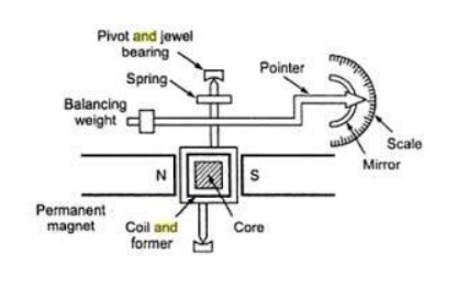
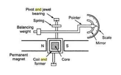
Stationary part or magnet system: In the
present time we use magnets of high field intensities, high coercive force instead of using U shaped permanent magnet having
soft iron pole pieces. The magnets which we are using nowadays are made up of
materials like alcomax and alnico which provide high field strength.
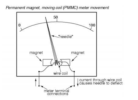
Moving coil: The moving coil can freely moves
between the two permanent magnets as shown
in the figure given below. The coil is wound with many turns of copper wire
and is placed on rectangular aluminum which is pivoted on jeweled bearings.
Control system: The spring generally acts as
control system for PMMC instruments. The spring also serves another important
function by providing the path to lead current in and out of the coil. Damping
system: The damping force hence torque is provided by movement of aluminium
former in the magnetic field created by the permanent magnets.
Meter: Meter of these instruments
consists of light weight pointer to have free movement and scale which is linear or uniform and varies with angle
Deflecting torque Equation:
Let us
derive a general expression for torque in permanent magnet moving coil
instruments or PMMC instruments. We know that in moving coil instruments the
deflecting torque is given
by the
expression:
Td = N B l dI
where N
is number of turns,
B is
magnetic flux density in air gap, l is the length of moving coil,
d is the
width of the moving coil, And I is the electric current.
Now for a
moving coil instruments deflecting torque should be proportional to current,
mathematically we can write Td = GI.
Thus on
comparing we say G = NBIdl.
At steady
state we have both the controlling and deflecting torques are equal.
Tc
is controlling torque, on equating controlling torque with deflection torque we
have GI = K.x where x is deflection thus current is given by
I = K / G x
Since the
deflection is directly proportional to the current therefore we need a uniform
scale on the meter for measurement of current.
Now we
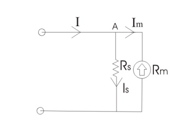
are going to discuss about the basic circuit diagram of the ammeter. Let us
consider a circuit as shown below:

The
current I is shown which breaks into two components at the point A. The two
components are Is and Im. Before I comment on the magnitude values of these
currents, let us know more about the construction of shunt resistance. The
basic properties of shuntresistance are written below,
The
electrical resistance of these shunts should not differ at higher temperature,
it they should posses very low value of temperature coefficient. Also the
resistance should be time independent. Last and the most important property
they should posses is that they should be able to carry high value of current
without much rise in temperature. Usually manganin is used for making dc
resistance. Thus we can say that the value of Is much greater than the value of
Im as resistance of shunt is low. From the we have,
Is .Rs =
ImRm
Where Rs
is resistance of shunt and Rm is the electrical resistance of the coil. Is = I
‚Äď Im
M= I / Im
= 1+ (Rm + Rs)
Where m
is the magnifying power of the shunt.
Errors in Permanent Magnet Moving Coil Instruments
There are
three main types of errors
(a) Errors due to permanent magnets:
Due to
temperature effects and aging of the magnets the magnet may lose their
magnetism to some extent. The magnets are generally aged by the heat and
vibration treatment.
(b) Error may appear in PMMC Instrument due to the
aging of the spring.
However
the error caused by the aging of the spring and the errors caused due to
permanent magnet are opposite to each other, hence both the errors are
compensated with each other.
(c) Change in the resistance of the moving coil
with the temperature:
Generally
the temperature coefficients of the value of coefficient of copper wire in
moving coil is 0.04 per degree Celsius rise in temperature. Due to lower value
of temperature coefficient the temperature rises at faster rate and hence the
resistance increases. Due to this significant amount of error is caused.
Advantages of Permanent Magnet Moving Coil
Instruments
(1)The
scale is uniformly divided as the current is directly proportional to
deflection of the pointer. Hence it is very easy to measure quantities from
these instruments.
(2)Power
consumption is also very low in these types of instruments. (3)Higher value of
torque is to weight ratio.
(4)These
are having multiple advantages, a single instrument can be used for measuring
various quantities by using different values of shunts and multipliers.
Disadvantages of Permanent Magnet Moving Coil
Instruments
(1) These instruments cannot measure ac
quantities.
(2) Cost of these instruments is high as
compared to moving iron instruments
Related Topics