Chapter: Digital Logic Circuits : Combinational Circuits
Magnitude Comparator
Magnitude Comparator
A magnitude comparator is a combinational
circuit that compares two given numbers and determines whether one is equal to,
less than or greater than the other. The output is in the form of three binary
variables representing the conditions A = B_A>B and A<B, if A and B are
the two numbers being compared. Depending upon the relative magnitude of the
two numbers, the relevant output changes state. If the two numbers, let us say,
are four-bit binary numbers and are designated as (A3 A2 A1 A0) and (B3 B2 B1
B0), the two numbers will be equal if all pairs of significant digits are equal,
that is, A3= B3, A2 = B2, A1= B1 and A0 = B0. In order to determine whether A
is greater than or less than B we inspect the relative magnitude of pairs of
significant digits, starting from the most significant position. The comparison
is done by successively comparing the next adjacent lower pair of digits if the
digits of the pair under examination are equal. The comparison continues until
a pair of unequal digits is reached. In the pair of unequal digits, if Ai = 1
and Bi = 0, then A > B, and if Ai = 0, Bi= 1 then A < B. If X, Y and Z
are three variables respectively representing the A = B, A > B and A < B
conditions, then the Boolean expression representing these conditions are given
by the equations
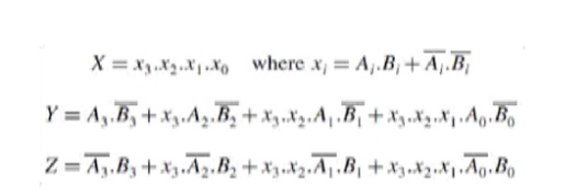
Let us examine equation (7.25). x3 will be ‘1‘ only when both A3 and B3 are equal. Similarly, conditions for x2, x1
and x0 to be ‘1‘
respectively are equal A2 and B2, equal A1 and B1 and equal A0 and B0. ANDing
of x3, x2, x1 and x0 ensures that X will be ‘1‘ when x3,
x2, x1 and x0 are in the logic ‘1‘ state. Thus, X = 1 means that A = B. On similar
lines, it can be visualized that equations (7.26) and (7.27) respectively
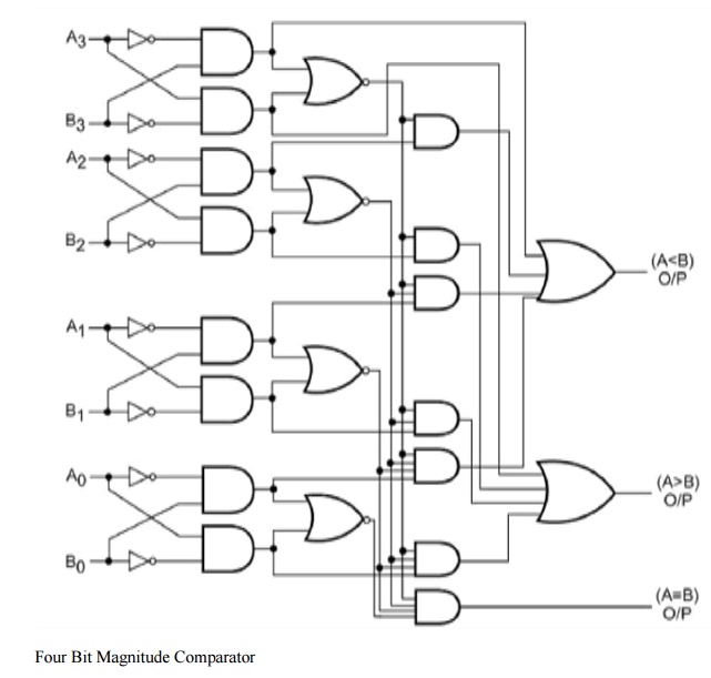
represent A > B and A < B conditions. Figure 7.36 shows the logic diagram
of a four-bit magnitude comparator.
Magnitude comparators are available in IC form.
For example, 7485 is a four-bit magnitude comparator of the TTL logic family.
IC 4585 is a similar device in the CMOS family. 7485 and 4585 have the same pin
connection diagram and functional table. The logic circuit inside these devices
determines whether one four-bit number, binary or BCD, is less than, equal to
or greater than a second four-bit number. It can perform comparison of straight
binary and straight BCD (8-4-2-1) codes. These devices can be cascaded together
to perform operations on larger bit numbers without the help of any external
gates. This is facilitated by three additional inputs called cascading or
expansion inputs available on the IC. These cascading inputs are also
designated as A = B, A > B and A < B inputs. Cascading of individual
magnitude comparators of the type 7485 or 4585 is discussed in the following
paragraphs. IC 74AS885 is another common magnitude comparator. The device is an
eight bit magnitude comparator belonging to the advanced Schottky TTL family.
It can perform high-speed arithmetic or logic comparisons on two eight-bit
binary or 2‘s complement numbers and produces two fully
decoded decisions at the output about one number being either greater than or
less than the other. More than one of these devices can also be connected in a
cascade arrangement to perform comparison of numbers of longer lengths.
Related Topics