Chapter: Digital Logic Circuits : Combinational Circuits
Karnaugh Map Method
Karnaugh Map Method
Maurice Karnaugh, a telecommunications engineer, developed the Karnaugh map at Bell Labs in 1953 while designing digital logic based telephone switching circuits. Karnaugh maps reduce logic functions more quickly and easily compared to Boolean algebra. By reduce we mean simplify, reducing the number of gates and inputs. We like to simplify logic to a lowest cost form to save costs by elimination of components. We define lowest cost as being the lowest number of gates with the lowest number of inputs per gate.
A Karnaugh map is a graphical representation of the logic system. It can be drawn directly from either minterm (sum-of-products) or maxterm (product-of-sums) Boolean expressions. Drawing a Karnaugh map from the truth table involves an additional step of writing the minterm or maxterm expression depending upon whether it is desired to have a minimized sum-of-products or a minimized product of-sums expression
Construction of a Karnaugh Map
An n-variable Karnaugh map has 2n squares, and each possible input is allotted a square. In the case of a minterm Karnaugh map, ‘1‘ is placed in all those squares for which the output is ‘1‘, and ‘0‘ is placed in all those squares for which the output is ‘0‘. 0s are omitted for simplicity. An ‘X‘ is placed in squares corresponding to ‘don‘t care‘ conditions. In the case of a maxterm Karnaugh map, a ‘1‘ is placed in all those squares for which the output is ‘0‘, and a ‘0‘ is placed for input entries corresponding to a ‘1‘ output. Again, 0s are omitted for simplicity, and an ‘X‘ is placed in squares corresponding to ‘don‘t care‘ conditions. The choice of terms identifying different rows and columns of a Karnaugh map is not unique for a given number of variables. The only condition to be satisfied is that the designation of adjacent rows and adjacent columns should be the same except for one of the literals being complemented. Also, the extreme rows and extreme columns are considered adjacent.
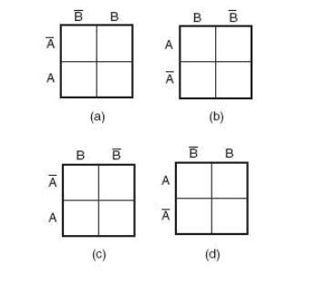
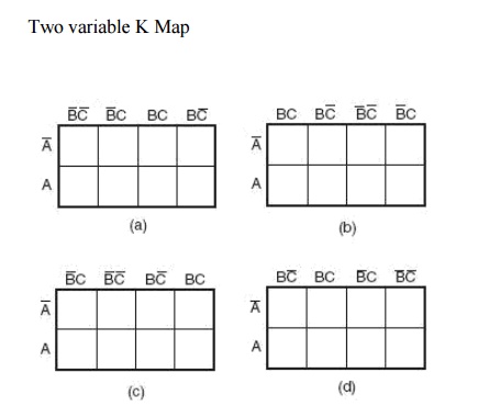
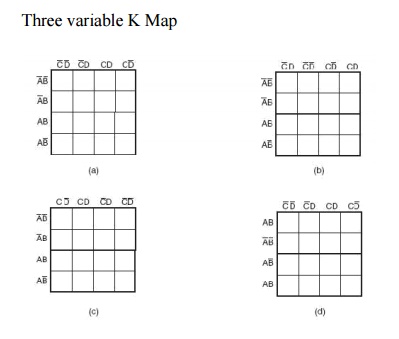
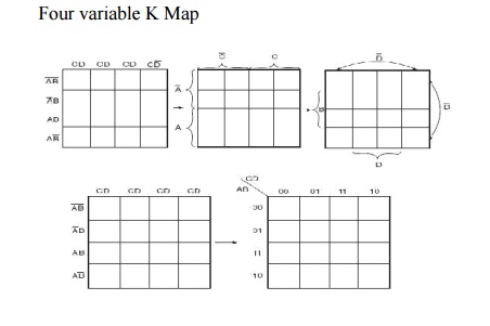
Some of the possible designation styles for two-, three- and four-variable minterm Karnaugh maps are shown in the figure below.
The style of row identification need not be the same as that of column identification as long as it meets the basic requirement with respect to adjacent terms. It is, however, accepted practice to adopt a uniform style of row and column identification. Also, the style shown in the figure below is more commonly used. A similar discussion applies for maxterm Karnaugh maps. Having drawn the Karnaugh map, the next step is to form groups of 1s as per the following guidelines:
1. Each square containing a ‘1‘ must be considered at least once, although it can be considered as often as desired.
2. The objective should be to account for all the marked squares in the minimum number of groups.
3. The number of squares in a group must always be a power of 2, i.e. groups can have 1,2, 4_ 8, 16, squares.
4. Each group should be as large as possible, which means that a square should not be accounted for by itself if it can be accounted for by a group of two squares; a group of two squares should not be made if the involved squares can be included in a group of four squares and so on.
5. ‘Don‘t care‘ entries can be used in accounting for all of 1-squares to make optimum groups. They are marked ‘X‘ in the corresponding squares. It is, however, not necessary to account for all ‘don‘t care‘ entries. Only such entries that can be used to advantage should be used.
Related Topics