Chapter: Digital Logic Circuits : Combinational Circuits
Decoders and Encoders
DECODERS AND ENCODERS
The previous section began by discussing an application: Given 2n data signals, the problem is to select, under the control of n select inputs, sequences of these 2n data signals to send out serially on a communications link. The reverse operation on the receiving end of the communications link is to receive data serially on a single line and to convey it to one of 2n output lines. This again is controlled by a set of control inputs. It is this application that needs only one input line; other applications may require more than one.We will now investigate such a generalized circuit.
Conceivably, there might be a combinational circuit that accepts n inputs (not necessarily 1, but a small number) and causes data to be routed to one of many, say up to 2n, outputs. Such circuits have the generic name decoder.
Semantically, at least, if something is to be decoded, it must have previously been encoded, the reverse operation from decoding. Like a multiplexer, an encoding circuit must accept data from a large number of input lines and convert it to data on a smaller number of output lines (not necessarily just one). This section will discuss a number of implementations of decoders and encoders.
n-to-2n-Line Decoder
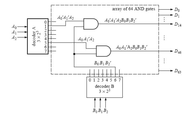
In the demultiplexer circuit in Figure 16, suppose the data input line is removed. (Draw the circuit for yourself.) Each AND gate now has only n (in this case three) inputs, and there are 2n (in this case eight) outputs. Since there isn‘t a data input line to control, what used to be control inputs no longer serve that function. Instead, they are the data inputs to be decoded. This circuit is an example of what is called an n-to-2n-line decoder. Each output represents a minterm. Output k is 1 whenever the combination of the input variable values is the binary equivalent of decimal k. Now suppose that the data input line from the demultiplexer in Figure 16 is not removed but retained and viewed as an enable input. The decoder now operates only when the enable x is 1. Viewed conversely, an n-to-2n-line decoder with an enable input can also be used as a demultiplexer, where the enable becomes the serial data input and the data inputs of the decoder become the control inputs of the demultiplexer.7 Decoders of the type just described are available as integrated circuits (MSI); n = 3 and n = 4 are quite common. There is no theoretical reason why n can‘t be increased to higher values. Since, however, there will always be practical limitations on the fan-in (the number of inputs that a physical gate can support), decoders of higher order are often designed using lower-order decoders interconnected with a network of other gates.
ENCODER
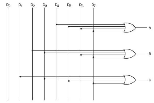
An encoder is a combinational circuit that performs the inverse operation of a decoder. If a device output code has fewer bits than the input code has, the device is usually called an encoder. e.g. 2n-to-n, priority encoders.
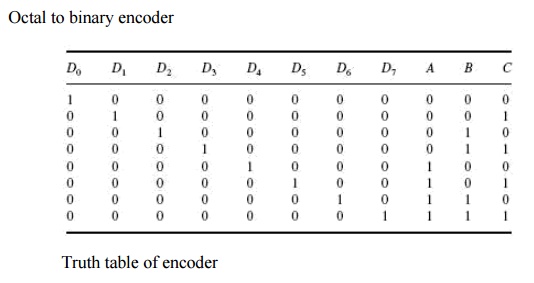
The simplest encoder is a 2n-to-n binary encoder, where it has only one of 2n inputs = 1 and the output is the n-bit binary number corresponding to the active input.
Priority Encoder
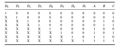
A priority encoder is a practical form of an encoder. The encoders available in IC form are all priority encoders. In this type of encoder, a priority is assigned to each input so that, when more than one input is simultaneously active, the input with the highest priority is encoded. We will illustrate the concept of priority encoding with the help of an example. Let us assume that the octal to-binary encoder described in the previous paragraph has an input priority for higher-order digits. Let us also assume that input lines D2, D4 and D7 are all simultaneously in logic ‘1‘ state. In that case, only D7 will be encoded and the output will be 111. The truth table of such a priority
encoder will then be modified to what is shown above in truth table. Looking at the last row of the table, it implies that, if D7 = 1, then, irrespective of the logic status of other inputs, the output is 111 as D7 will only be encoded. As another example, Fig. 8.16 shows the logic symbol and truth table of a 10-line decimal to four-line BCD encoder providing priority encoding for higher-order digits, with digit 9 having the highest priority. In the functional table shown, the input line with highest priority having a LOW on it is encoded irrespective of the logic status of the other input lines.
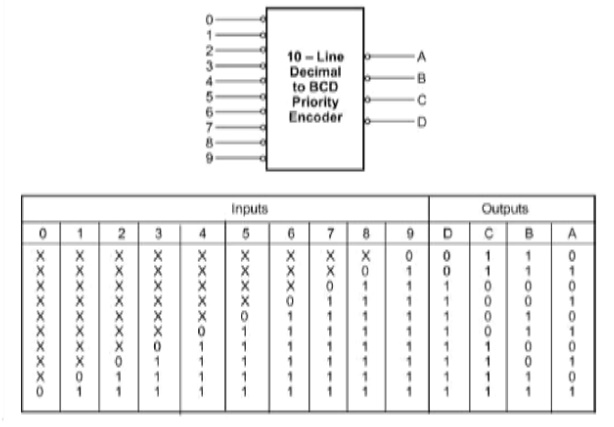
10 line decimal to four line BCD priority encoder
Some of the encoders available in IC form provide additional inputs and outputs to allow expansion. IC 74148, which is an eight-line to three -line priority encoder, is an example. ENABLE-IN (EI) and ENABLE-OUT (EO) terminals on this IC allow expansion. For instance, two 74148s can be cascaded to build a 16-line to four-line priority encoder.
Related Topics