Chapter: Digital Logic Circuits : Combinational Circuits
Combinational Logic Design
COMBINATIONAL LOGIC DESIGN
Introduction
The term 'combinational' comes to us from mathematics. In mathematics a combination is an unordered set, which is a formal way to say that nobody cares which order the items came in. Most games work this way, if you rolled dice one at a time and get a 2 followed by a 3 it is the same as if you had rolled a 3 followed by a 2. With combinational logic, the circuit producesthe same output regardless of the order the inputs are changed. There are circuits which depend on the when the inputs change, these circuits are called sequential logic. Even though you will not find the term ‖sequential logic‖ in the chapter titles, the next several chapters will discuss sequential logic. Practical circuits will have a mix of combinational and sequential logic, with sequential logic making sure everything happens in order and combinational logic performing functions like arithmetic, logic, or conversion.
Design Using Gates
A combinational circuit is one where the output at any time depends only on the present combination of inputs at that point of time with total disregard to the past state of the inputs. The logic gate is the most basic building block of combinational logic. The logical function performed by a combinational circuit is fully defined by a set of Boolean expressions. The other category of logic circuits, called sequential logic circuits, comprises both logic gates and memory elements such as flip-flops. Owing to the presence of memory elements, the output in a sequential circuit depends upon not only the present but also the past state of inputs.
The Fig shows the block schematic representation of a generalized combinational circuit having n input variables and m output variables or simply outputs. Since the number of input variables is
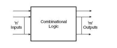
Generalized Combinational Circuit
n, there are 2n possible combinations of bits at the input. Each output can be expressed in terms of input variables by a Boolean expression, with the result that the generalized system of above fig can be expressed by m Boolean expressions. As an illustration, Boolean expressions describing the function of a four-input OR/NOR gate are given as

BCD Arithmetic Circuits
Addition and subtraction are the two most commonly used arithmetic operations, as the other two, namely multiplication and division, are respectively the processes of repeated addition and repeated subtraction, as was outlined in Chapter 2 dealing with binary arithmetic. We will begin with the basic building blocks that form the basis of all hardware used to perform the aforesaid arithmetic operations on binary numbers. These include half-adder, full adder, half-subtractor, full subtractor and controlled inverter.
Related Topics