Chapter: Mobile Computing
MAC Protocols
MAC PROTOCOLS
The Medium Access Control (MAC) protocol is used to provide the data link layer of the Ethernet LAN system. The MAC protocol encapsulates a SDU (payload data) by adding a 14 byte header (Protocol Control Information (PCI)) before the data and appending an integrity checksum, The checksum is a 4-byte (32-bit) Cyclic Redundancy Check (CRC) after the data. The entire frame is preceded by a small idle period (the minimum inter-frame gap, 9.6 microsecond (µS)) and a 8 byte preamble (including the start of frame delimiter).
Preamble
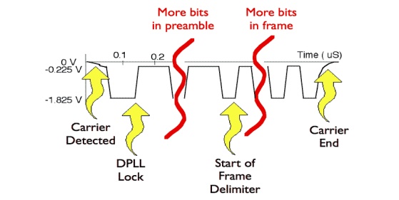
The purpose of the idle time before transmission starts is to allow a small time interval for the receiver electronics in each of the nodes to settle after completion of the previous frame. A node starts transmission by sending an 8 byte (64 bit) preamble sequence. This consists of 62 alternating 1's and 0's followed by the pattern 11. Strictly speaking the last byte which finished with the '11' is known as the "Start of Frame Delimiter". When encoded using Manchester encoding, at 10 Mbps, the 62 alternating bits produce a 10 MHz square wave (one complete cycle each bit period).

The purpose of the preamble is to allow time for the receiver in each node to achieve lock of the receiver Digital Phase Lock Loop which is used to synchronise the receive data clock to the transmit data clock. At the point when the first bit of the preamble is received, each receiver may be in an arbitrary state (i.e. have an arbitrary phase for its local clock). During the course of the preamble it learns the correct phase, but in so doing it may miss (or gain) a number of bits. A special pattern is therefore used to mark the last two bits of the preamble. When this is received, the Ethernet receive interface starts collecting the bits into bytes for processing by the MAC layer. It also confirms the polarity of the transition representing a '1' bit to the receiver (as a check in case this has been inverted).
Header

data The header consists of three parts:
A 6-byte destination address, which specifies either a single recipient node (unicast mode), a group of recipient nodes (multicast mode), or the set of all recipient nodes (broadcast mode).
A 6-byte source address, which is set to the sender's globally unique node address. This may be used by the network layer protocol to identify the sender, but usually other mechanisms are used (e.g.arp). Its main function is to allow address learning which may be used to configure the filter tables in a bridge.
A 2-byte type field, which provides a Service Access Point (SAP) to identify the type of protocol being carried (e.g. the values 0x0800 is used to identify the IP network protocol, other values are used to indicate other network layer protocols).
CRC
The final field in an Ethernet MAC frame is called a Cyclic Redundancy Check (sometimes also known as a Frame Check Sequence). A 32-bit CRC provides error detection in the case where line errors (or transmission collisions in Ethernet) result in corruption of the MAC frame. Any frame with an invalid CRC is discarded by the MAC receiver without further processing. The MAC protocol does not provide any indication that a frame has been discarded due to an invalid CRC.
The link layer CRC therefore protects the frame from corruption while being transmitted over the physical medium (cable). A new CRC is added if the packet is forwarded by the router on another Ethernet link. While the packet is being processed by the router the packet data is not protected by the CRC. Router processing errors must be detected by network or transport-layer checksums.
Inter Frame Gap
After transmission of each frame, a transmitter must wait for a period of 9.6 microseconds (at 10 Mbps) to allow the signal to propagate through the receiver electronics at the destination. This period of time is known as the Inter-Frame Gap (IFG). While every transmitter must wait for this time between sending frames, receivers do not necessarily see a "silent" period of 9.6 microseconds. The way in which repeaters operate is such that they may reduce the IFG between the frames which they regenerate.
Byte Order
It is important to realise that nearly all serial communications systems transmit the least significant bit of each byte first at the physical layer. Ethernet supports broadcast, unicast, and multicast addresses. The appearance of a multicast address on the cable (in this case an IP multicast
address, with group set to the bit pattern 0xxx xxxx xxxx xxxx xxxx xxxx) is therefore as shown below (bits transmitted from left to right):

1 = Assigned for other uses
However, when the same frame is stored in the memory of a computer, the bits are
ordered such that the least significant bit of each byte is stored in the right most position (the bits are transmitted right-to-left within bytes, bytes transmitted left-to-right):

Related Topics