Chapter: Mobile Computing : Mobile Telecommunication System
Universal Mobile Telecommunication System
UNIVERSAL MOBILE
TELECOMMUNICATION SYSTEM
The Universal Mobile Telecommunications System
(UMTS) is a third generation mobile cellular system for networks based on the
GSM standard. Developed and maintained by the 3GPP (3rd Generation Partnership
Project), UMTS is a component of the Standard International Union all IMT-2000
telecommunications and compares it with the standard set for CDMA2000 networks
based on competition cdma One technology. UMTS uses wideband code division
multiple access (W-CDMA) radio access technology to provide greater spectral
efficiency and bandwidth mobile network operators.
Network Evolution
An Evolution that Makes Sense
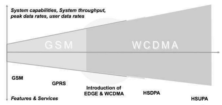
HSUPA : High
Speed Uplink Packet Access
HSDPA : High
speed downlink packet access
The main idea behind 3G is to prepare a universal
infrastructure able to carry existing and also future services. The
infrastructure should be so designed that technology changes and evolution can
be adapted to the network without causing uncertainties to the existing
services using the existing network structure.
WCDMA Technology
The first Multiple Access Third Generation
Partnership Project (3GPP) Wideband Code Division networks (WCDMA) were
launched in 2002. At the end of 2005, there were 100 WCDMA networks open and a
total of more than 150 operators with licenses for frequencies WCDMA operation.
Currently, WCDMA networks are deployed in UMTS band of around 2 GHz in Europe
and Asia, including Japan and America Korea.
WCDMA is deployed in the 850 and 1900 of the
existing frequency allocations and the new 3G band 1700/2100 should be
available in the near future. 3GPP has defined WCDMA operation for several
additional bands, which are expected to be commissioned in the coming years. As
WCDMA mobile penetration increases, it allows WCDMA networks to carry a greater
share of voice and data traffic.
WCDMA
technology provides some advantages for the operator in that it allows the
data, but also improves the voice of base. Voice capacity offered is very high
due to interference control mechanisms, including frequency reuse of 1, fast
power control, and soft handover. WCDMA can offer a lot more voice minutes to
customers. Meanwhile WCDMA can also improve broadband voice service with AMR codec,
which clearly provides better voice quality than fixed telephone landline. In
short, WCDMA can offer more voice minutes with better quality.
In addition to the high spectral efficiency,
third-generation (3G) WCDMA provides even more dramatic change in capacity of
the base station and the efficiency of the equipment. The high level of
integration in the WCDMA is achieved due to the broadband carrier: a large
number of users supported by the carrier, and less radio frequency (RF)
carriers are required to provide the same capacity.
With less RF parts and more digital baseband
processing, WCDMA can take advantage of the rapid evolution of digital signal
processing capability. The level of integration of the high base station
enables efficient building high capacity sites since the complexity of RF
combiners, additional antennas or power cables can be avoided. WCDMA operators
are able to provide useful data services, including navigation, person to
person video calls, sports and video and new mobile TV clips.
WCDMA enables simultaneous voice and data which
allows, for example, browsing or email when voice conferencing or video sharing
in real time during voice calls.
The
operators also offer mobile connectivity to the Internet and corporate intranet
with maximum bit rate of 384 kbps downlink and both uplink. The first terminals
and networks have been limited to 64 to 128 kbps uplink while the latter
products provide 384 kbps uplink.
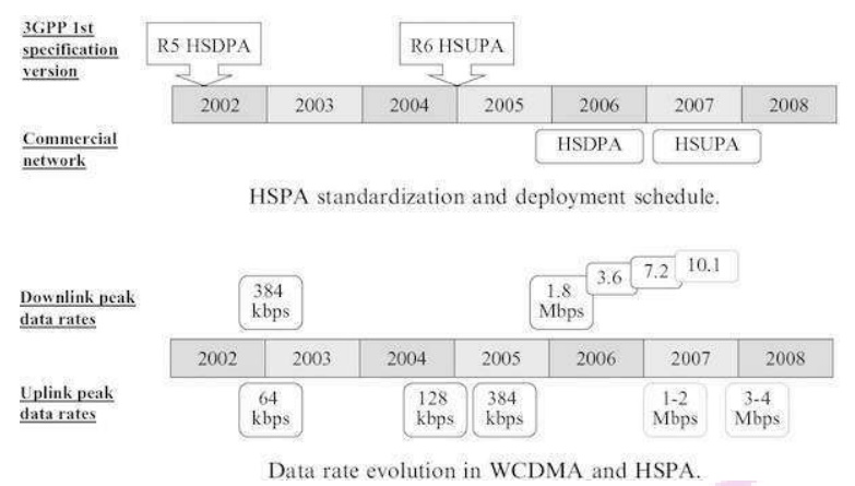
HSPA Standardization
High-speed
downlink packet access (HSDPA) was standardized as part of 3GPP Release 5 with
the first specification version in March 2002. High-speed uplink packet access
(HSUPA) was part of 3GPP Release 6 with the first specification version in
December 2004. HSDPA and HSUPA together are called High-Speed Packet Access‘
(HSPA).
The first commercial HSDPA networks were available
at the end of 2005 and the commercial HSUPA networks were available on 2007.
The HSDPA peak data rate available in the terminals is initially 1.8Mbps and
will increase to 3.6 and 7.2 Mbps during 2006 and 2007, and later on 10Mbps and
beyond 10Mbps. The HSUPA peak data rate in the initial phase was 1–2 Mbps and
the second phase was 3–4Mbps.
HSPA is deployed over the WCDMA network on the same
carrier or - for high capacity and high speed solution - using another carrier.
In both cases, WCDMA and HSPA can share all the network elements in the core
network and the radio network comprising base stations, radio network
controller (RNC), Serving GPRS Support Node (SGSN) and the Gateway GPRS Support
Node (GGSN). WCDMA and HSPA also share the site base station antennas and
antenna cables.
The upgrade WCDMA HSPA requires new software and
potentially new equipment in the base station and RNC to support the rate and
higher data capacity. Because of the shared infrastructure between WCDMA and
HSPA, the cost of the upgrade WCDMA HSPA is very low compared to the
construction of a new stand-alone data network.
UMTS - Radio Interface and Radio
Network Aspects
After the
introduction of UMTS the amount of wide area data transmission by mobile users
had picked up. But for the local wireless transmissions such as WLAN and DSL,
technology has increased at a much higher rate. Hence, it was important to
consider the data transmission rates equal to the category of fixed line
broadband, when WIMAX has already set high targets for transmission rates. It
was clear that the new 3GPP radio technology Evolved UTRA (E-UTRA, synonymous
with the LTE radio interface) had to become strongly competitive in all respect
and for that following target transmission rates were defined:
· Downlink:
100 Mb/s
· Uplink:
50 Mb/s
Above numbers are only valid for a reference
configuration of two antennas for reception and one transmit antenna in the
terminal, and within a 20 MHz spectrum allocation.
UMTS – All IP Vision
A very general principle was set forth for the
Evolved 3GPP system. It should ―all IP‖, means that the IP connectivity is the
basic service which is provided to the users. All other layer services like
voice, video, messaging, etc. are built on that. Looking at the protocol stacks
for interfaces between the network nodes, it is clear that simple model of IP
is not applicable to a mobile network.
There are virtual layers in between, which is not
applicable to a mobile network. There are virtual layer in between, in the form
of ―tunnels‖, providing the three aspects - mobility, security, and quality of
service. Resulting, IP based protocols appear both on the transport layer
(between network nodes) and on higher layers.
UMTS – Requirements of the New
Architecture
There is a new architecture that covers good
scalability, separately for user plane and control plane. There is a need for
different types of terminal mobility support that are: fixed, nomadic, and
mobile terminals. The minimum transmission and signalling overhead especially
in air, in an idle mode of the dual mode UE signalling should be minimized, in
the radio channel multicast capability.
It is required to be reused or extended, as roaming
and network sharing restrictions, compatible with traditional principles
established roaming concept, quite naturally, the maximum transmission delay
required is equivalent to the fixed network, specifically less than 5
milliseconds, set to control plane is less than 200 milliseconds delay target.
Looking at the evolution of the 3GPP system in
full, it may not seem less complex than traditional 3GPP system, but this is
due to the huge increase in functionality. Another strong desire is to arrive
at a flat structure, reducing CAPEX/OPEX for operators in the 3GPP architecture
carriers.
Powerful control functions should also be
maintained with the new 3GPP systems, both real-time seamless operation (for
example, VoIP) and non-real-time applications and services. The system should
perform well for VoIP services in both the scenarios. Special attention is also
paid to the seamless continuity with legacy systems (3GPP and 3GPP2), supports
the visited network traffic local breakout of voice communications.
UMTS – Security and Privacy
Visitor Location Register (VLR) and SNB are used to
keep track of all the mobile stations that are currently connected to the
network. Each subscriber can be identified by its International Mobile
Subscriber Identity (IMSI). To protect against profiling attacks, the permanent
identifier is sent over the air interface as infrequently as possible. Instead,
local identities Temporary Mobile Subscriber force (TMSI) is used to identify a
subscriber whenever possible.
Each UMTS subscriber has a dedicated home network
with which it shares a secret key Ki long term. The Home Location
Register (HLR) keeps track of the current location of all the home network
subscribers. Mutual authentication between a mobile station and a visited
network is carried out with the support of the current GSN (SGSN) and the MSC /
VLR, respectively. UMTS supports encryption of the radio interface and the
integrity protection of signalling messages.
UMTS – WCDMA Technology
The first
Multiple Access Third Generation Partnership Project (3GPP) Wideband Code
Division networks (WCDMA) were launched in 2002. At the end of 2005, there were
100 WCDMA networks open and a total of more than 150 operators with licenses
for frequencies WCDMA operation. Currently, WCDMA networks are deployed in UMTS
band of around 2 GHz in Europe and Asia, including Japan and America Korea.
WCDMA is deployed in the 850 and 1900 of the existing frequency allocations and
the new 3G band 1700/2100 should be available in the near future. 3GPP has defined
WCDMA operation for several additional bands, which are expected to be
commissioned in the coming years.
As WCDMA
mobile penetration increases, it allows WCDMA networks to carry a greater share
of voice and data traffic. WCDMA technology provides some advantages for the
operator in that it allows the data, but also improves the voice of base. Voice
capacity offered is very high due to interference control mechanisms, including
frequency reuse of 1, fast power control, and soft handover.
WCDMA can
offer a lot more voice minutes to customers. Meanwhile WCDMA can also improve
broadband voice service with AMR codec, which clearly provides better voice
quality than fixed telephone landline. In short, WCDMA can offer more voice
minutes with better quality.
In
addition to the high spectral efficiency, third-generation (3G) WCDMA provides
even more dramatic change in capacity of the base station and the efficiency of
the equipment. The high level of integration in the WCDMA is achieved due to
the broadband carrier: a large number of users supported by the carrier, and
less radio frequency (RF) carriers are required to provide the same capacity.
With less
RF parts and more digital baseband processing, WCDMA can take advantage of the
rapid evolution of digital signal processing capability. The level of
integration of the high base station enables efficient building high capacity
sites since the complexity of RF combiners, additional antennas or power cables
can be avoided. WCDMA operators are able to provide useful data services,
including navigation, person to person video calls, sports and video and new
mobile TV clips.
WCDMA
enables simultaneous voice and data which allows, for example, browsing or
email when voice conferencing or video sharing in real time during voice calls.
The
operators also offer mobile connectivity to the Internet and corporate intranet
with maximum bit rate of 384 kbps downlink and both uplink. The first terminals
and networks have been limited to 64 to 128 kbps uplink while the latter products
provide 384 kbps uplink.
WCDMA-3G
3G
wireless service has been designed to provide high data speeds, always-on data
access, and greater voice capacity. Listed below are a few notable points: The
high data speeds, measured in Mbps, enable full motion video, high-speed
internet access and video-conferencing. 3G technology standards include UMTS,
based on WCDMA technology (quite often the two terms are used interchangeably)
and CDMA2000, which is the outgrowth of the earlier CDMA 2G technology.
UMTS
standard is generally preferred by countries that use GSM network. CDMA2000 has
various types, including 1xRTT, 1xEV-DO and 1xEV-DV. The data rates they offer
range from 144 kbps to more than 2 mbps.
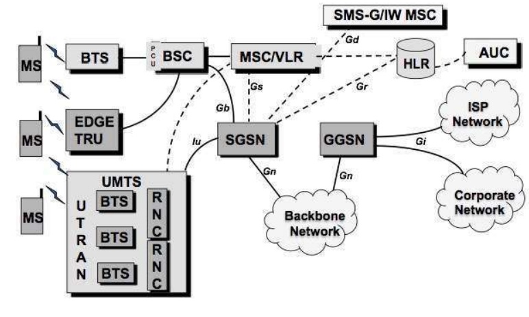
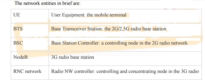
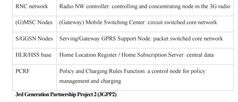
Sub-systems of 3G Network
A GSM
system is basically designed as a combination of three major subsystems:
·
Network Subsystem (NSS): MSC/VLR, HLR, AuC, SMSC,
EIR, MGW. Common for both 2G & 3G Network.
·
UTRAN: RNC & RBS.
·
Operation and maintenance Support Subsystem (OSS).
There are
three dominant interfaces, namely,
·
IuCS: Between RNC and MSC for speech & Circuit
data;
·
IuPS: Between RNC & SGSN for packet data;
·
Uu interface: Between the RNC and MS.
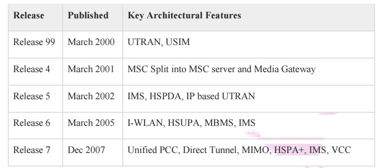
UMTS – 3GPP
3rd Generation Partnership Project or
3GPP, is the standardization group for mobile networks and is in existence
since 1998. 3GPP specification come in bundles called
―Release‖.
3rd Generation
Partnership Project (3GPP)
3GPP
releases are from Release 99 to Release 7.
3GPP2 is the corresponding part of 3GPP market.
3GPP2 standards body has also developed a large set of specifications
describing own mobile network technology, the current generation being labelled
as CDMA2000 ©. 3GPP2 is 3GPP concepts and solutions, but is chosen selectively
different. Regarding LTE, there has been a growing interest of 3GPP2 operators
in recent years to allow between flexible and efficient. The inheritance 3GPP2
technology includes a component called 1xRTT CS and PS component (EVDO vs
eHRPD). 3GPP2 consider their (eHRPD) high-speed packet data network as
equivalent to 3GPP old system, the right to transfer procedures optimized
specially designed.
Architecture of the 3GPP System
The overall architecture of the 3GPP, evolved
system as well as the core and access networks already existing 3GPP defined
are called "legacy 3GPP system".
The
access networks which are not defined by the 3GPP, but may be used in
conjunction with the evolved 3GPP system are called "non-3GPP access
networks".
The area of service must be understood as the
multitude of IP services, so in general they are represented and implemented by
packet data networks (PDN). IP service can simply offer a raw IP connectivity
(i.e. allowing an internet connection), providing a connection to a corporate
network, or an advanced IP-based control functionality such as telephony and
instant messaging via IMS.
It is called "Evolved UTRAN" (EUTRAN).
GERAN and UTRAN are the existing radio access networks and are connected to the
legacy PS domain. Evolved Packet Core (EPC) in addition to the basic functions
to manage packet routing and forwarding (for the transport of user data)
contains all the features necessary to control especially for mobility, session
handling, safety and load.
For interworking with legacy CS domain, the CS core
network should be considered as well and interfaced with the backend IMS. The
dotted arrow indicates an optional interconnection between legacy CS core
networks and the new network Evolved Packet Core, the decline in profit to the
CS domain for voice services, if necessary.
UMTS – Radio Access Network
The more
general term "Evolved Radio Access Network" (eRAN), can also be used
as part of signalling protocols, as the term "access stratum" (AS)
can be used. The comparison reveals that E-UTRAN consists of one type of nodes,
namely Evolved Node B (eNodeB), and the variety of interconnections is reduced
to a minimum. eNodeB is a radio base station and transmits/receives via its
antenna in an area (cell), limited by physical factors (signal strength,
interference conditions, and conditions of radio wave propagation). It has
logical interfaces X2 with neighbouring eNodeB and the EPC via S1.
Both have a control part (that is, say for
signalling) and a user plane part (for payload data). Point to the EU reference
(which includes radio link interface and a mobile network protocol stack bound)
is called "LTE-U u" to indicate that it differs from the legacy
counterpart EU X2 connectivity neighbouring eNodeBs. They may be considered for
most of the E-UTRAN and is used in most cases of handovers between radio cells.
As the UE moves, long handover preparation is done
via signalling, through X2 between the two data eNodeBs and affected users can
be transmitted between them for a short period of time. Only in special cases,
it may happen that X2 is not configured for eNodeB between two neighbours. In
this case transfers are always supported, but the preparation of transfer and
the data transmission is then made via the EPC. Accordingly, higher latency and
less "homogeneity" must therefore be provided.
In more
detail, the functions performed by the eNodeB are:
·
Radio Resource Management: Radio Bearer Control,
Radio Admission Control, Connection Control Mobility, dynamic allocation of
resources (i.e. scheduling) to UES as uplink and downlink.
·
Header compression of IP and encryption of user
data stream.
·
Forwarding the data packets of user plane to the
EPC (especially, toward the GW node service).
·
Transport level packet marking in the uplink, for
example, DiffServ code point setting, based on the QoS class index (QCI) of the
EPS bearer associated.
·
Planning and delivery of paging messages (on
request of MS).
·
Planning and transmission of broadcast information
(origin of the MME or O & M).
·
Measurement configuration delivering and reporting
on the extent of mobility and programming.
UMTS – evolved packet core
By the
early architectural work for the system evolved 3GPP, two views on the
implementation of mobility with the user plane and control plane protocols were
presented. The first was promoted as the good performance of the GPRS
Tunnelling Protocol (GTP), while the other pushed for the new (and the
so-called "base" of the IETF) protocols.
Both had
good arguments on their side:
·
GTP
evolution : This protocol has proven its usefulness and capabilities to operators, and was very successful in the large
scale operations. It was designed exactly to the needs of the mobile networks
PS.
·
IETF
based protocols : IETF is the de facto standards body for the
internet. Their mobility protocols
have evolved from focusing on mobile IP-based network client to "Proxy
Mobile IP (MIP)." PMIP was standardized in 3GPP Evolved parallel system.
(But Mobile IP client base is used in EPS in conjunction with non-3GPP access
support.)
EPC for 3GPP access in non-roaming
The
functions provided by the reference points and the protocols employed are:
LTE-Uu
LTE-Uu is
the point of reference for radio interface between EU and eNodeB, encompasses
control plane and user plane. The top layer of the control plan is called
"Radio Resource Control" (RRC). It is stacked on "Packet Data
Convergence Protocol" (PDCP), Radio Link Control and MAC layers.
S1-U
SI-U is
the point for user plane traffic between eNodeB and serve GW reference. The
main activity via this benchmark is to transfer IP packets encapsulated users
arising from traffic or tunnel shape. Encapsulation is needed to realize the
virtual IP link between eNodeB and GW service, even during the movement of EU,
and thus enable mobility. The protocol used is based on GTP-U.
S1-MME
S1-MME is
the point for the control plane between eNodeB and MME reference. All control
activities are carried out on it, for example, signalling for attachment,
detachment, and the establishment of the support of the change, safety
procedures, etc. Note that some of this traffic is transparent to the E-UTRAN
and is exchanged directly between EU and MS, it is a part called
"non-access stratum" (NAS) signalling.
S5
S5 is the
benchmark that includes the control and user plane between GW and PDN GW
Service and applies only if both nodes reside in the HPLMN; the corresponding
reference point when serving GW is VPLMN is called S8. As explained above, two
protocol variants are possible here, an enhanced GPRS Tunnelling Protocol (GTP)
and Proxy Mobile IP (PMIP).
S6a
S6a is
the reference point for the exchange of information relating to subscriptions
equipment (download and purging). It corresponds to Gr and D reference point in
the existing system, and is based on the DIAMETER protocol.
SGi
This is
the point of exit for DPR, and corresponds to the Gi reference point GPRS and
Wi in I-WLAN. IETF protocols are based here for the user plane (i.e. IPv4 and
IPv6 packet forwarding) protocols and control plane as DHCP and radius/diameter
for configuring IP address/external network protocol are used.
S10
S10 is a
reference point for the MME relocation purposes. It is a pure control plane
interface and advanced GTP-C protocol is used for this purpose.
S11
S11 is a
reference point for the existing control plane between MME and GW service. It
employs the advanced GTP-C (GTP-C v2) protocol. The holder(s) of data between
eNodeB and serve GW are controlled by the concatenation S1-S11 and MME.
S13
S13 is
the reference point for Equipment Identity Register (EIR) and MME, and it is
used for identity control (e.g. based on IMEI, if blacklisted). It uses the
diameter protocol SCTP.
Gx
Gx is the
reference point of the QoS policy filtering policy and control the load between
PCRF and PDN GW. It is used to provide filters and pricing rules. The protocol
used is the DIAMETER.
Gxc
Gxc is
the reference point that exists in over Gx but is located between GW and PCRF
and serves only if PMIP is used on S5 or S8.
Rx
Rx is
defined as an application function (AF), located in NDS and PCRF for the
exchange of policy and billing information; it uses the DIAMETER protocol.
EPC for 3GPP Access in Roaming
In
roaming this case the user plane either:
Extends
back to the HPLMN (via an interconnection network), which means that all EU
user traffic is routed through a PDN GW in the HPLMN, where the DPRs are
connected;
or For
the sake of a more optimal way of traffic, it leaves a PDN GW in the VPLMN to a
local PDN.
The first
is called "home routed traffic" and the second is called "local
breakout". (Note that the second term is also used in the discussion of
traffic optimization for home NBs/eNodeB, but with a different meaning because
in the concept of roaming 3GPP, the control plan always involves the HPLMN).
Interworking between EPC and Legacy
From the
beginning, it was clear that the 3GPP Evolved system will interoperate
seamlessly with existing 2G and 3G systems, 3GPP PS widely deployed or, more
precisely, with GERAN and UTRAN GPRS base (For aspects of interworking with the
old CS system for the treatment of optimized voice).
The
question of the basic architectural design to 2G/3G in EPS is the location of
the GGSN map. Two versions are available, and both are supported:
·
The GW
used : It is the normal case where serving the GW ends the user plane (as seen in the existing GPRS network).The
control plan is completed in the MME, according to the distribution of users
and control plane in EPC. S3 and S4 reference points are introduced, and they
are based on GTP-U and GTP-C, correspondingly. S5/S8 is chained to the PDN GW.
The advantage is that interoperability is smooth and optimized. The downside is
that for this kind of interoperability SGSN must be upgraded to Rel. 8 (due to
the necessary support new features on S3 and S4).
·
The PDN
GW : In this
case the unchanged benchmark inheritance Gn (when roaming, it would Gp) is reused between SGSN and PDN GW, for both control
and user plane. The advantage of this use is that SGSN can be pre-Rel. 8.
Furthermore, it carries a certain restriction on IP versions, transfer and S5 /
S8 protocol.
Interworking with Legacy 3GPP CS
System
During
the 3GPP Evolved design phase, it became clear that the legacy CS system, with
its most important service "voice" communication, could not be
ignored by the new system. The operators were simply too related investments in
the field, and so very efficient interworking was requested.
Two
solutions have been developed:
Single
Radio Voice Call Continuity (SRVCC) for transferring voice calls from LTE (with
voice over IMS) to the legacy system.
·
CS fallback: Enabling a temporary move to the
legacy CS before a CS incoming or outgoing activity is performed.
Single Radio Voice Call Continuity (SRVCC)
In this
solution chosen by 3GPP for SRVCC with GERAN/UTRAN, a specially reinforced MSC
is connected via a new interface control plane for MME. Note that the MSC
serving the EU can be different than supporting the Sv interface. In the IMS,
an application server (AS) for SRVCC is necessary. Sv is based on GTPv2 and
helps prepare resources in the target system (access and core network and the
interconnection between CS and IMS domain), while being connected to access the
source.
Similarly,
with SRVCC CDMA 1xRTT requires interworking 1xRTT Server (IWS), which supports
the interface and signal relay from / to 1xRTT MSC serving the UE S102 with the
same purpose. S102 is a tunnel interface and transmits 1xRTT signaling
messages; between MME and UE these are encapsulated.
CS Fallback
Serving
GW and PDN GW are not separated (S5/S8 is not exposed) and the VLR is
integrated with the MSC server. A new SG interface is introduced between the
MSC Server/VLR and MME, allowing combined and coordinated procedures. The
concept consists of:
·
Signal relay to end the CS request (incoming calls,
handling network triggered additional service or SMS Legacy) from the MSC
Server for MS on SG and vice versa;
·
The combined operating procedures between the PS
domain and the CS domain.
Interworking with Non-3GPP Access
Interworking
with different system of 3GPP access networks (called non-3GPP/access) was an
important target for SAE; this should be done under the EPC umbrella. This
interoperability can be achieved at different levels (and in fact, this was
done on the layer 4 with VCC/SRVCC). But for the generic type of interworking,
it seemed necessary to rely on generic mechanisms, so the IP level seemed most
appropriate.
In
general, complete systems for mobile and fixed networks have an architecture
similar to that described above. For the evolved 3GPP system there is normally
an access network and a core network. In the interworking architecture
scheduled evolved 3GPP system, other access technologies systems connect to the
EPC.
In
general, complete mobile network system and fixed network systems have a
similar architecture as described outlined in Evolved 3GPP system and normally
consist of an access network and a core network/ It was also decided to allow
two different types of interoperability, based on the property of the access
systems. For networks with non-3GPP access confidence, it is assumed that
secure communication between them and the EPC is implemented and also robust
data protection is sufficiently guaranteed.
UMTS – GPRS Tunnelling Protocol
The
generation of GPRS Tunnelling Protocol (GTP) was virtually impossible, but is
also not desirable to give it for the new system, but, on the other hand, it is
quite understandable that the improvements are also needed in order to be able
to interact with the world of legacy PS smoothly and support functions needed
for the newest system.
GPRS Tunnelling Protocol (GTP)
GTP
protocol is designed for tunnelling and encapsulation of data units and control
messages in GPRS. Since its design in the late 1990s, it was put to deploy on a
large scale, and solid experience has been gathered. GTP for Evolved 3GPP
system is available in two variants, control and user plane. GTP-C manages the
control plane signalling, and it is necessary in addition to the data transfer
protocol on the purity of the user, GTP-U; it is called user plane. Current
versions, suitable for EPS are GTPv1 US and GTPv2-C.
The
peculiarity of GTP is that it supports the separation of traffic within its
primary GTP tunnel holder, or in other words, the ability to group them
together and treat carriers. The ends of GTP tunnels are identified by TEIDs
(Tunnel Endpoint identifiers); they are assigned to the local level for the
uplink and downlink by peer entities and reported transversely between them.
TEIDs are used on different granularity by specific example PDN connection on
S5 and S8 and EU on S3 / S4 / S10 / S11 interfaces.
Control Plane of GPRS Tunnelling
Protocol
GTPv2-C
is used on the EPC signalling interfaces (including SGSNs of at least Rel. 8).
For
example:
·
S3 (between SGSN and MME),
·
S4 (between SGSN and Serving GW),
·
S5 and S8 (between Serving GW and PDN GW),
·
S10 (between two MMEs), and
·
S11 (between MME and Serving GW).

Corresponding to this, a typical GTPv2-C protocol
data unit like shown in the figure above, the specific part GTP is preceded by
IP and UDP headers, it consists of a header GTPv2-C and part containing
information GTPv2-C variable in number, length and format, depending on the
type of the message. As the echo and the notification of a protocol version is
not supported, TEID information is not present. The version is obviously firmly
set at 2 in this version of the protocol.
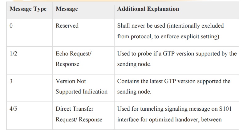
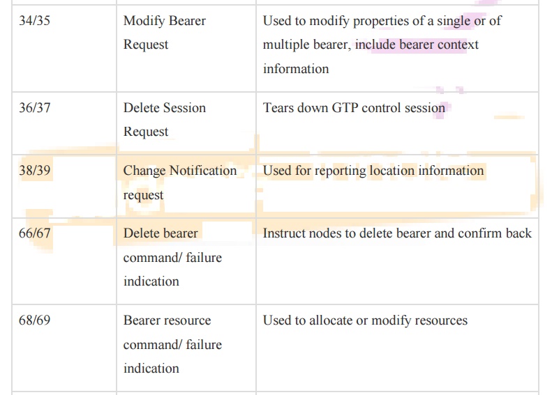
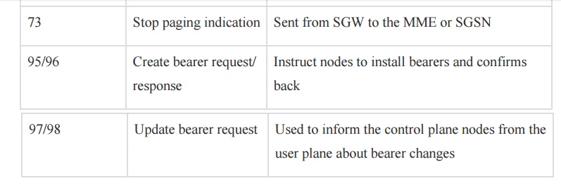
GTP had a complex legacy extension header
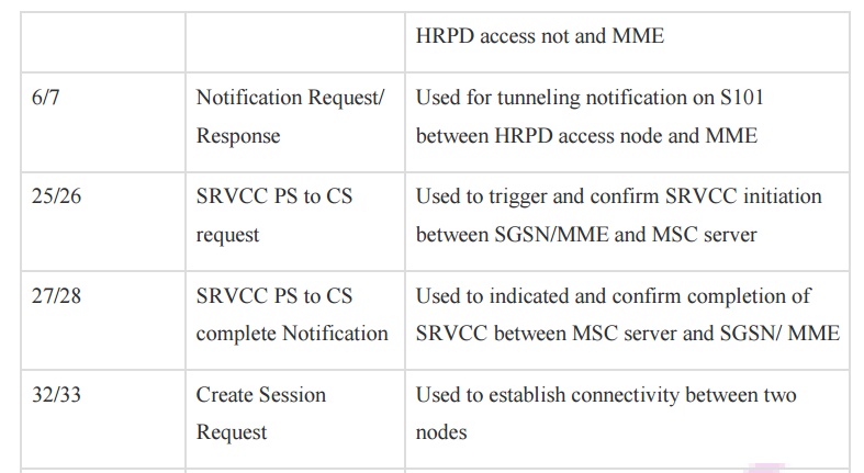
mechanism; it is not used in most GTPv2-C. The message type is defined in the
second byte (so the maximum of 256 messages can be defined for future
extensions). Below table provides an overview of messages currently defined
GTPv2-C. The length of the message is coded in bytes 3 and 4 (measured in bytes
and not containing the first four bytes themselves).
TEID is the ID of the tunnel end point, a single
value on the opposite/receiving side; it allows multiplexing and
de-multiplexing tunnels at one end in the very frequent cases over a GTP tunnel
must be distinguished.
Enhanced GTPv1-U
Only a small but effective improvement was applied
to GTP-U, and for that it was not considered necessary to strengthen the number
of protocol version. Thus, we still expect GTPv1-U, but at least it‘s most
recent Rel. 8.
The
protocol stack is essentially the same as for GTPv2-C with only the name of the
layers and the protocols substituted accordingly. The extension header
mechanism is kept in place; it allows inserting two elements if necessary.
·
UDP source port of the triggering message (two
octets);
·
PDCP PDU number: related to the characteristic transfer
without loss; in this case, data packets need to be numbered in the EPC (two
octets).
The improvement is the ability to transmit an
"end market" in the user plane. It is used in the inter-eNodeB
handover procedure and gives the indication that the pathway is activated
immediately after the data packet, for example, the feature is not necessary to
pre-Rel.8 because GTP-U did not end in the radio access node (i.e. not in the
BS or NodeB) only a few messages exist. GTPv1-U, and they are listed in the
table above.
It is clear that, in fact a very limited kind of
signaling is possible via GTPv1-U (echo mechanisms and end labeling). The only
message that the transfer of real user data is of type 255, the so-called G-PDU
message; the only piece of information it carries, after the header is the
original data packet from a user or external PDN equipment.
Not all instances of GTP-U tunnels are listed in
the reference architecture (which aimed to capture the associations were no
longer living between network nodes); temporary tunnels are possible:
·
Between two Serving GWs, applicable for the
transfer based on S1, in the case that the service is moved GW;
·
Between two SGSNs, corresponds to the previous
case, but in the legacy PS network;
·
Between two RNCs, applicable for the relocation of
the RNC in the 3G PS network (no relation to the EPC, it is mentioned here just
for completeness).
Related Topics