Chapter: Embedded Systems Design : Interrupts and exceptions
Interrupt latency
Interrupt latency
One of the most important aspects of using interrupts is in the latency.
This is usually defined as the time taken by the processor from recognition of
the interrupt to the start of the ISR. It consists of several stages and is
dependent on both hardware and software factors. Its importance is that it
defines several aspects of an embedded system with reference to its ability to
respond to real-time events. The stages involved in calculating a latentcy are:
•
The time taken to recognise the
interrupt
Do not asssume that this is instantaneous as it will depend on the
processor design and its own interrupt recognition mechanism. As previously
mentioned, some processors will repeatedly sample an interrupt signal to ensure
that it is a real one and not a false one.
•
The time taken by the CPU to
complete the current instruc-tion
This will also vary depending on what the CPU is doing and its
complexity. For a simple CISC processor, this time will vary as its
instructions all take a different number of clocks to complete. Usually the
most time-consuming instructions are those that perform multiplication or
division or some complex data manipulation such as bit field operations. For
RISC processors with single cycle execution, the time is usually that to clear
the execution pipeline and is 1 or 2 clocks. For complex processors that
execute multiple in-structions per clocks, this calculation can get quite
difficult. The other problem is identifying which instruction will be executing
when the interrupt is recognised. In practice, this is impossible to do and the
worst case execution time is used. This can often be one or more orders of
magnitude greater than a typical instruction. A 32 bit division could take
several hundred clocks while a simple add or subtract could be 1 cycle. Some
compilers will restrict the use of multiple cycle instructions so that these
worst case figures can be improved by only using fast executing instructions.
As part of this, division and multiplication are often per-formed by software
routines using a sequence of faster add, subtract and bit manipulation
instructions. Of course, if the code is being written in assembly, then this
can be finely tuned by examining the instruction mix.
•
The time for the CPU to perform a
context switch
This is the time taken by the processor to save its internal context
information such as its program counter, internal data registers and anything
else it needs. For CISC proces-sors, this can involve creating blocks of data
on the stack by writing the information externally. For RISC processors this
may mean simply switching registers internally without explicitly saving any
information. Register windowing or shadowing is normally used.
•
The time taken to fetch the
interrupt vector
This is normally the time to fetch a single value from memory but even
this time can be longer than you think! We will come back to this topic.
•
The time taken to start the
interrupt service routine execu-tion
Typically very short. However remember that because the pipeline is
cleared, the instruction will need to be clocked through to execute it and this
can take a few extra clocks, even with a RISC architecture.
In practice, processor architectures will have different precedures for
all these stages depending on their design philosphy and sophistication.
With a simple microcontroller, this calculation is simple: take the
longest execution time for any instruction, add to it the number of memory
accesses that the processor needs times the number of clocks per access, add
any other delays and you arrive with a worst case interrupt latency. This
becomes more difficult when other factors are added such as memory management
and caches. While the basic calculations are the same, the number of clocks
involved in a memory access can vary dramatically — often by an order of
magnitude! To correctly calculate the value, the interupt latency calculations
also have to take into account the cost of external memory access and this can
sometimes be the over-whelmingly dominant factor.
While all RISC systems should be designed with single cycle memory
access for optimum performance, the practicalities are that memory cycles often
incur wait states or bus delays. Unfortunately for designers, RISC
architectures cannot tolerate such delays — one wait state halves the
performance, two reduces performance to a third. This can have a dramatic
effect on real-time performance. All the advantages gained with the new
architecture may be lost.
The solution is to use caches to speed up the memory access and remove
delays. This is often used in conjunction with memory management to help
control the caches and ensure data coher-ency, as well as any address
translation. However, there are some potential penalties for any system that
uses caches and memory management which must be considered.
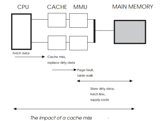
Consider the system in the diagram. The processor is using a Harvard
architecture with combined caches and memory man-agement units to buffer it
from the slower main memory. The caches are operating in copyback mode to
provide further speed improvements. The processor receives an interrupt and
immedi-ately starts exception processing. Although the internal context is
preserved in shadow registers, the vector table, exception routines and data
exist in external memory.
In this example, the first data fetch causes a cache miss. All the cache
lines are full and contain some dirty data, therefore the cache must update
main memory with a cache line before fetching the instruction. This involves an
address translation, which causes a page fault. The MMU now has to perform an
external table walk before the data can be stored. This has to complete before
the cache line can be written out which, in turn, must complete before the
first instruction of the exception routine can be executed. The effect is
staggering — the quick six cycle interrupt latency is totally overshadowed by
the 12 or so memory accesses that must be completed simply to get the first
instruction. This may be a worst case scenario, but it has to be considered in
any real-time design.
This problem can be contained by declaring exception routines and data
as non-cachable, or through the use of a BATC or transparent window to remove
the page fault and table walk. These techniques couple the CPU directly to
external memory which, if slow, can be extremely detrimental to performance.
Small areas of very fast memory can be reserved for exception handling to solve
this problem; locking routines in cache can also be solutions, at the expense
of performance in other system functions. It should be of no surprise that many
of today's RISC controllers are using local memory (tightly coupled memory or
TCM) to store interrupt routines and thus allow the system designer to address
the latency problems of caches and memory management. This is added to the
processor and resides on-chip. Access does not require any off-chip bus cycles
and so it will not slow down the processor whenever it is used. By locating the
time critical routines and data in this tightly coupled memory, it is possible
to not only reduce the latency and ISR execution time but also make the
execution more consistent in its timing.
Related Topics