Chapter: Pharmaceutical Drug Analysis: Gas Liquid Chromatography (GLC)
Instrumentation - High Performance Liquid Chromatography (HPLC)
INSTRUMENTATION
Modern HPLC essentially comprises of the following main
components namely :
(i) Solvent
reservoir and degassing system,
(ii) Pressure,
flow and temperature,
(iii) Pumps and
sample injection system,
(iv) Columns,
(v) Detectors,
(vi) Strip-chart
recorder, and
(vii) Data
handling device and microprocessor control.
All these vital components will be discussed with
adequate details, wherever necessary, in the various sections that follow :
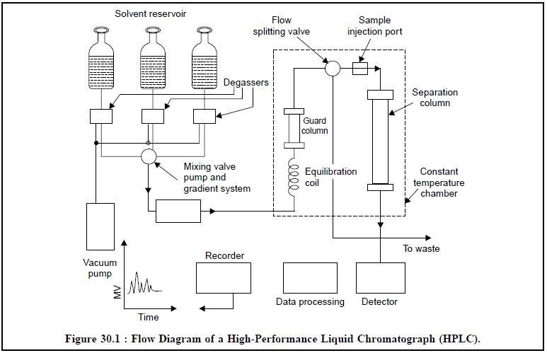
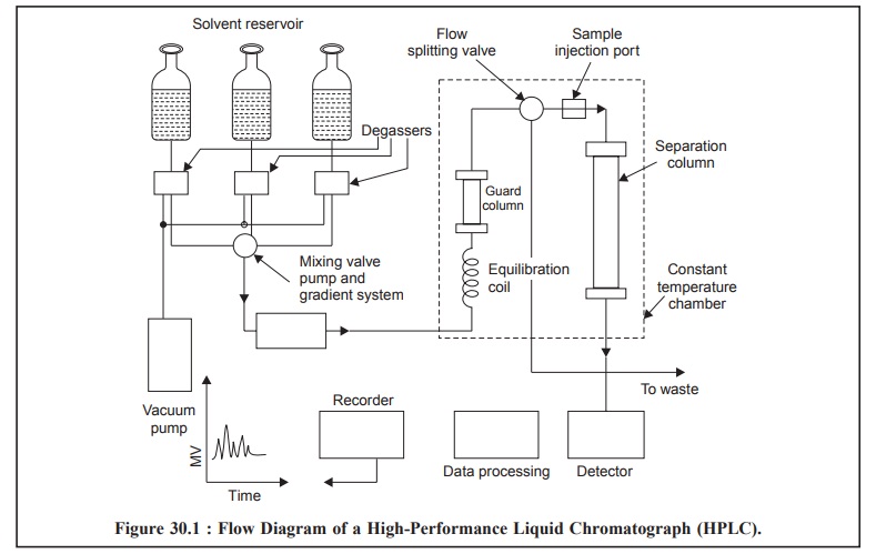
The Figure 30.1, illustrates the flow diagram of a high
performance liquid chromatograph, wherein all the vital components have been
duly represented.
The mobile phase, that may be either a single liquid or a
mixture of two or more liquids, is pumped at high pressure into a temperature
controlled oven, where it first, gains its entry into an equilibration coil to
bring it to the operating temperature, and secondly, through a ‘guarded column’
specially designed and strategically positioned to protect the analytical
column from impurities and ultimately extend its lifetime.
1. SOLVENT RESERVOIR AND DEGASSING SYSTEM
Mobile phase consisting of mixture of organic solvents or
an aqueous-orgainc mixture or a buffer solution may be employed depending upon
the chromatograohic method vis-a-vis the detector to be used.
2. PRESSURE, FLOW AND TEMPERATURE
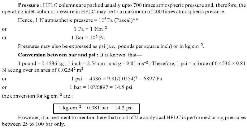
There are, in fact, several factors that are solely
responsible for the ‘pressure’
developed in a column, namely :
(a) the length
of the column,
(b) particle
size of the stationary phase,
(c) viscosity
of the mobile-phase, and
(d) flow-rate
of the mobile-phase.
The pressures mentioned above correspond to mobile-phase
flow rates of approximately 1-5 cm3 min–1 through the column.
Flow : The flow can be measured
periodically at the column outlet by collecting the liquid for a known period, and thereafter, either
measuring the volume or weighing it physically.
Temperature : In reality, the maintenance of
strict ‘temperature control’ plays a vital role in measuring the retention-data correctly and
precisely. It makes use of the refractometer detectors specifically. In HPLC,
difficult separations may be achieved by increasing the temperature carefully,
but this must be done initially on a hit and trial basis.
3 PUMPS AND SAMPLE INJECTION SYSTEM
Pumps : The two major functions of the pump in a modern HPLC are, namely :
(i) To pass the
mobile-phase through the column at a high pressure, and
(ii) At a
constant a controlled flow rate.
HPLC makes use of two types of pumps. They are :
(a) Constant Pressure Pump : A
constant-pressure pump acts by applying a constant pressure to the
mobile-phase. The flow rate through the column is determined by the flow
resistance of the column.
(b) Constant Flow Pump : A constant-flow
pump affords and maintains a given flow of liquid. The pressure developed
entirely depends upon the flow resistance.
Importantly, in a constant-pressure pump the flow rate
will change if the flow resistance changes. Whereas in the constant flow pumps
the changes in flow resistance are compensated duly by a change of pressure.
Therefore, it is always advisable to use constant flow pump in HPLC
determinations.
Salient features of HPLC pump are as follows :
(i) Interior of
the pump must not be corroded by any solvent to be used in the system,
(ii)
Variable-flow-rate device must be available to monitor flow rate,
(iii) Solvent
flow must be non-pulsing,
(iv) Changing
from one mobile-phase to another must be convenient, and
(v) It should
be easy to dismantle and repair.
The pump is a very delicate and sensitive part of HPLC
unit ; therefore, all buffer solutions should be removed carefully after use
either by pumping water (HPLC-grade) or an appropriate solvent (HPLC-grade) for
several minutes.
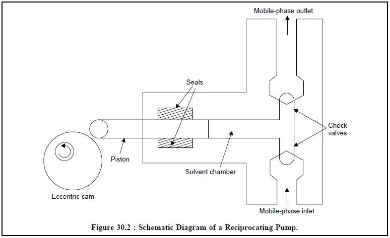
Reciprocating Pump : Figure 30.2 represents the
schematic diagram of a typical reciprocating pump along with its various essential components. The piston is moved
in and out of a solvent chamber by an eccen-tric cam or gear. The
forward-stroke closes the inlet-check value while the outlet valve opens and
the respective mobile phase is duly pumped into the column. Consequently, the
return-stroke-closes the outlet valve and it refills the chamber.
Advantages : It has the following
advantages, namely :
(i) It has an
unlimited capacity,
(ii) The
internal-volume can be made very small from 10-100 μ l,
(iii) The
flow-rate can be monitored either by changing the length of the piston or by
varying the speed of the motor, and
(iv) It has an easy access to
the valves and seals.
The use of twin-head reciprocating pump (i.e., having the two heads operated 180°
out of phase) func-tions in such a manner that while one head is pumping, the
other is refilling as could be seen in Figure 30.3.
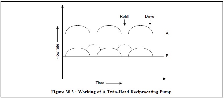
In Figure 30.3, the flow rate of a twin-head reciprocal
pump has been plotted against time. The stage-A depicts the drive while the
refill zone is vacant ; while the stage-B evidently shows the two-heads
functioning simultaneously thereby the drive and the refill both zones could be
visualized.
Sample Injection System : There are in all three different modes of sample injection
system that are used in HPLC, namely
:
(a) Septum Injectors : They usually permit
the introduction of the sample by a high pressure syringe through a
self-sealing elastometer septum. The major drawback associated with this type
of injec-tors is ‘leaching effect’
of the mobile-phase just in contact with the septum, thereby resulting in the
formation of ‘ghost peaks’ or ‘pseudo peaks’. In short, in HPLC the
mode of syringe injection brings about more problems than in GC.
(b) Stop-flow Septumless Injection : Here,
most of the problems associated with septum-injectors have been duly
eliminated. The flow of the mobile-phase through the column is stopped for a
while, and when the column reaches an ambient pressure the top of the column is
opened and the sample introduced at the top of the packing.
The first two methods are relatively very cheap.
(c) Microvolume Sampling Valves : Highly
sophisticated modern HPLC frequently make use of microvolume sampling valves
for injection which not only give fairly good precision, but also are adaptable
for automatic injection. These valves enable samples to be introduced
reproducibly into pressurized columns without causing the least interruption of
the mobile-phase flow.
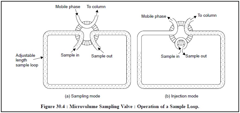
Figure 30.4, displays the operation of a sample loop in
two different modes i.e., (a) sampling mode and (b) injection mode. Here, the sample is
loaded at atmospheric pressure into an external loop in the
microvolume-sampling valve, and subsequently injected into the mobile-phase by
a suitable rotation to the valve. However, the volume of sample introduced
usually ranges between 2 µl to over 100 µl ; but can be varied either by
altering the volume of the sample loop or by employing specific variable-volume
sample valves.
Therefore, it is always preferred for most quantitative
work by virtue of its very high degree of precision and accuracy.
4. COLUMNS
(a) Dimensions and Fillings : Following are
the various dimensions of HPLC columns :
Material:
Stainless-steel (highly polished surface)
External Diameter: 6.35
mm (or ≡ 0.25 inch),
Internal Diameter: 4-5
mm (usual : 4.6 mm), and
Length: 10-3 cm (usual :
25 cm).
(b) Fittings : Each end of the column is
adequately fitted with a stainless-steel gauze or frit with a mesh of 2 μ m or less so as to retain the packing material (usually
having a particle diameter 10, 5 and 3 μ m).
A stainless-steel-reducing union for a column of ID 4.6
mm type makes use of a 1/4-1/6 inch union with a short length of 0.25 mm (or
0.01 inch) ID ptfe tube so as to connect the column to the detector.
In actual practice, three conventional reducing unions
available are employed, namely :
(i) Large Dead Volume (LDV)) Union :
Loss of efficiency,
(ii) Zero Dead Volume (ZDV) Union :
Loss of efficiency, and
(iii) Low Dead Volume (LDV) Union :
Most efficient, most expensive, and dead-volume 0.1 μ l.
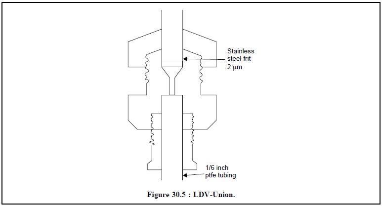
Figure 30.5 depicts the diagram of a typical LDV-Union
having a SS-frit of 2 μ m and a ptfe tubing of 1/6
inch.
(i)
Performance : Inside a column the
concentration of a band of solute decreases as it moves through the system. The
column performance or the efficiency of a column entirely depends on the amount
of spreading that takes place. The measurement is represented in Figure 30.6,
below :
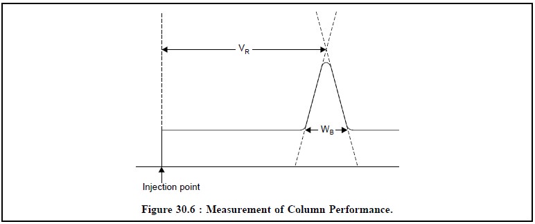
The efficiency or
performance of a column may be measured by the following expression :
N = 16(VR/WB)2 ...(a)
H = L/N ...(b)
VR = Retention volume of a solute,
WR = Volume occupied by a solute (or ‘Peak-Width’). Evidently, for a more
efficient column, WB will be smaller at a given value of VR,
H= Plate number of the column
(dimensionless), H = Plate height of the column (mm × μ m), and L = Length of the column (cm).
Based on Eq. (b)
one may clearly observe that for a more efficient column ‘N’ gets larger and
corre-spondingly ‘H’ gets smaller.
(iii) Types of Packing : Modern HPLC makes
use of packing which essentially consist of small and rigid particles with a
very narrow particle size distribution. Broadly speaking three types of packing
are invariably used in HPLC column, namely :
(a) Styrene-divinylbenzene copolymers based
porous polymeric beads have been employed exclusively for size-exclusion and
ion-exchange chromatography, but now mostly been replaced by silica-based
packings that proved to be more efficient and mechanically stable.
(b) Porous-layer beads with a diameter
ranging between 30-35 μ m comprising of a thin shell
(1-3 μ m) of silicon or modified
silica, on an inert spherical core material, such as : glass beads are still
being employed for certain ion-exchange procedures ; but of late their usage as
such in HPLC have been superseded by 100% porous microparticulate packings, and
(c) Porous-silica particles (100%) with a
diameter less than 1 μ m and narrow-particle size
range, nowadays, form the basis of most abundantly available important column
packings used in analytical HPLC. In comparison to the porous-layer beads, as
detailed in (b) above, the
porous-silica particles yield significant improvements not only in column
efficiency but also in sample capacity and speed of analysis.
5. DETECTORS
The main function of the detector in HPLC is to monitor
the mobile-phase coming out of the column, which in turn emits electrical
signals that are directly proportional to the characteristics either of the
solute or the mobile-phase.
The various detectors often used in HPLC may be
categorized into three major heads,
namely :
(i) Bulk-property detectors : They
specifically measure the difference in some physical property of the solute
present in the mobile-phase in comparison to the individual mobile-phase, for
instance :
(a)
Refractive-index detectors, and
(b)
Conductivity detectors.
(ii) Solute-property detectors. They
critically respond to a particular physical or chemical characteristic of the
solute (in question), which should be ideally and absolutely independent of the
mobile-phase being used. But complete independence of the mobile-phase is
hardly to be seen, however, signal discrimination is good enough to enable
distinctly measurable experimental procedures with solvent changes, such as :
gradient-elution.
The solute-property detectors include :
(a)
UV-detectors, and
(a)
Fluorescence Detectors.
(iii) Multipurpose detectors : Besides,
providing a high degree of sensitivity* together with a
broad-linear-response-attainable range, invariably a particular situation
critically demands detectors of more selective nature in the domain of
‘analytical chemistry’ vis-a-vis
‘Pharmaceutical Analysis’ that could be accomplished by using ‘multipurpose
detectors’, such as : “Perkin-Elmer ‘3D’
Sys-tem” that combines UV absorption, fluorescence and conductometric
detection.
(iv) Electrochemical detectors :
‘Electrochemical detector’ in HPLC usually refers to either amperometric or
coulometric detectors, that specifically measure the current associated with
the reduction or oxidation of solutes. As only a narrow spectrum of compounds
undergo electrochemical oxidation, such detectors are quite selective ; and
this selectivity may be further enhanced by moni-toring the potential applied
to the detector so as to differentiate between various electroactive spe-cies.
Naturally, electrochemical detection essentially makes use of conducting mobile
phases, for instance : inorganic salts or mixtures of water with water-miscible
organic solvents.
The five important
types of detectors shall be discussed along with their simple diagrammatic
sketches, in the sections that follow :
5.1. UV-Detectors
Principle : An UV-detector is based on the
principle of absorption of UV visible light from the effluent emerging out of the column and passed
though a photocell placed in the radiation beam.
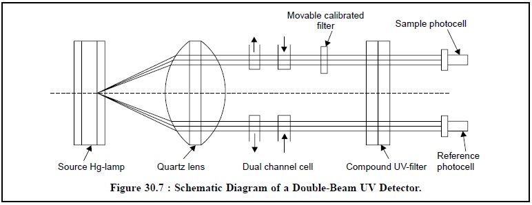
Figure 30.7 represents the schematic diagram of a
double-beam UV detector used in HPLC system. Initially, dual-wavelength
instruments having 254 and/or 280 nm were introduced which is presently being
replaced by more sophisticated and up-dated variable wavelength detectors
spread over wide range between 210-800 nm capable of performing more selective
detection possible.
Diode Array Detector (or Multichannel Detector) is also a UV detector wherein a
polychromatic light is made to pass
through the flow cell. A strategically placed grating diffracts the outcoming
radiation and subsequently meets an array of photodiodes whereby each
photodiode receives a different narrow wavelength band. Here, a microprocessor
scans the array of diodes several times in one second and the resulting
spectrum is visualized on the screen of a VDU or subsequently stored in the
instrument for a printout as and when required. Another extremely important and
useful characteristic feature of a diode-array detector is that it may be
‘programmed’ so as to affect changes in the detection wavelength at particular
points in the chromatogram. This versatile criterion is used to ‘clean up’ a chromatogram i.e., to discard all interfering peaks
caused due to components irrelevantly present in the sample.
Advantages : Various advantages are, namely
:
(a) A very
selective detector which will detect only such solutes that specifically absorb
UV/visible radiation e.g., alkenes,
aromatics and compounds having multiple bonds between C, O, N and S.
(b) The
mobile-phase* employed ideally must not absorb any radiation.
5.2. Fluorescence Detector
A plethora of compounds (solutes) present in the
mobile-phase on being passed as column effluent through a cell irradiated with
Xenon or Deuterium source first absorb UV radiation and subsequently
emit-radiation of a longer wavelength in two different manners, namely :
(a)
Instantly-termed as ‘Fluorescence’,
and
(b) After a time-gap-known
as ‘Phosphorescence’.
Fluorescent compounds : A relatively small proportion
of inorganic and organic compounds exhibit
natural fluorescence, whereas a larger number of pharmaceutical substances
and environmental contaminants [e.g.,
polycyclic aromatic hydrocarbons (PAH)] having a conjugated-cyclic system are
fluorescent. Such com-pounds having absorbed energy being re-emitted from
0.1-1.0 can be detected by a fluorescence detector. However, non-fluorescent
compounds can be converted to fluorescent derivatives by treatment with
appropri-ate solvents.
Figure 30.8, illustrates the diagram of a fluorescence
detector :
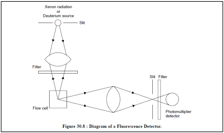
Radiation from a Xenon-radiation or a Deuterium-source is
focussed on the flow cell through a filter. The fluorescent radiation emitted
by the sample is usually measured at 90° to the incident beam. The second
filter picks up a suitable wavelength and avoids all scattered light to reach
ultimately the photomultiplier detector.
5.3. Refractive Index Detector
It is also known as ‘RI-Detector’
and ‘Refractmeter’. Figure 30.9,
represents the block-diagram of a refractive-index detector.
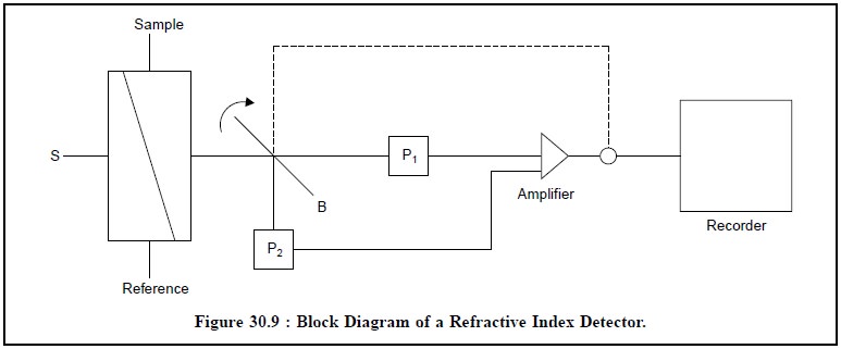
Light from the source(s) is focused into the cell, that
consists of sample and reference sample ; and the two chambers are separated by
a diagonal sheet of glass. After passing through the cell, the light is
diverted by a beam-splitter (B) to two photocells (P1 and P2
respectively. A change in the observed refractive index (RI) of the sample
stream causes a difference in their relative output, which is adequately
amplified and recorded duly.
The RI of a few commonly used mobile-phase is stated
below :

Any solute can be detected as long as there exists a
measurable difference in refractive index between the solute and the
mobile-phase.
5.4. Multipurpose Detector
A multipurpose detector essentially comprises of three
detectors combined and housed together in a single unit. A typical example of
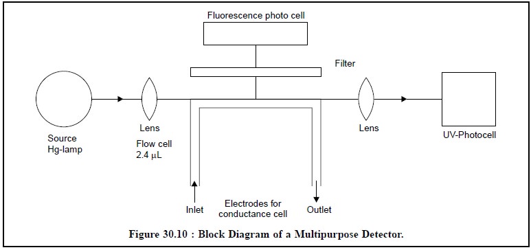
such a detector is the one developed by Perkin-Elmer known as “Perkin-Elmer ‘3D’ System” which is
depicted in Figure 30.10.
The functions of the three different detectors used in
Figure 30.10 are enumerated as under :
(i) Fluorescence Function : It can monitor
emission above 280 nm, based on excitation at 254 nm,
(ii) UV-Function : It is fixed wavelength
254 nm detector, and
(ii)
Conductance-Function : The metal inlet and outlet
tubes serve as electrodes to measure the con-ductance of the ions.
5.5. Electrochemical Detectors
In actual practice, however, it is rather difficult to
utilize the functions of electrochemical reduction as a means of detection of
HPLC by virtue of the fact that the serious interference (i.e., large background current) generated by reduction of oxygen in
the mobile phase. As complete removal of oxygen is almost difficult, therefore,
electrochemical detection is normally based upon the oxidation of the solute.
Examples : The various compounds that may
be detected conveniently are, namely : aromatic amines, phenols, ketones, and
aldehydes and heterocyclic nitrogen compounds.
In short, the amperometric
detector is presently considered to be the best electrochemical detector
having the following distinct advantages, such as :
(i) very small
internal cell-volume,
(ii) high
degree of sensitivity,
(iii) more
limited range of applications, and
(iv) excellent
for trace analyses as UV-detector lacks adequate sensitivity.
Table 30.2, provides a comprehensive comparison of
various typical detector characteristics invariably used in HPLC, such as :
response, concentration expressed in g ml–1 and the linear range.
However, the linear range usually refers to the range over which the response
is essentially linear. It is mostly expressed as the factor by which the lowest
factor (i.e., Cn) should be
multiplied in order to obtain the highest concentration.

6. STRIP CHART RECORDER
The signal emerging from the detector of a HPLC is
recorded continuously as function of time most commonly with the help of a
potentiometric recorder. Invariably, a recorder of 1 to 10 mV full-scale deflec
tion over a stretch of approximately ten inches and having a response-time of
one second or even less is regarded as most appropriate. Strip-chart recorder
with variable chart speeds ranging between 5 to 5 mm min–1 are
usually preferred.
The input signal of a potentiometric-recorder is balanced
continuously with the help of a feedback signal arrangement (device) using a servomechanism. A pen attached to this
device moves proportionately, with preadjusted attenuation, along the width of
the chart-paper thereby recording the signal accurately, while the chart-paper
moves at a fixed speed along the length.
It is pertinent to mention here that before commencing
the operation of a recorder, its zero point must be adjusted with the input
zero, otherwise the baseline will also shift with slight changes in the
attenuation of the signal.
Besides, it is also equally important to adjust properly
the amplifier gain so as to eliminate completely the dead-band and the
oscillations. A recorder having inadequate shielding from the AC circuits may
display shifting of its zero point.
7. DATA HANDLING DEVICE AND MICROPROCESSOR CONTROL
Modern HPLC is adequately provided with complete data
handling devices. Thousands of samples routinely analysed in Quality Assurance
Laboratories in Pharmaceutical Industries/Bulk Drug Industries etc. are duly
processed and the data stored in the computerised data-handling devices. Each
stored data may be retrieved from the memory of the computerised device with
the flick of a finger, as and when needed, in the form of print-out.
Microprocessor based analytical equipments is no longer
an uncommon phenomenon towards the mod-ernization, automation, and above all
the ease of function and handling of sophisticated devices, for instance : a
microprocessor scans the array of diodes many times a second in a ‘diode array detector’ ; a
microproces-sor does the temperature programming of a constant temperature
chamber of HPLC unit.
Related Topics