Chapter: Mechanical : Computer Integrated Manufacturing
Group Technology and Computer Aided Process Planning
GROUP TECHNOLOGY AND COMPUTER AIDED PROCESS
PLANNING
Group technology (GT) is a
philosophy that implies the notion of recognizing and exploiting similarities
in three different ways:
1. By
performing like activities together
2. By
standardizing similar tasks
3. By
efficiently storing and retrieving information about recurring problems
Large manufacturing system can be decomposed into smaller
subsystems of part families based on similarities in design attributes and
manufacturing features.
Concept of Group technology;
Group technology is a
manufacturing philosophy in which similar parts are identified and grouped
together to take the advantage of their similarities in manufacturing and design.
Similar parts are arranged in to part families.
Advantages
of group technology
·
Product design benefits- 10 % reduction in the
number of drawings
·
Tooling and setup benefits – 69 %
reduction of setup time.
·
Materials handling benefits
·
Production and inventory control benefits
·
-70 % reduction in production time
·
-62 % reduction in work in process inventories
·
-82 % reduction in overdue orders
·
Employee satisfaction
·
Process planning procedures
Group technology (GT);
Group technology (GT) is a
manufacturing philosophy to increase production efficiency by grouping a
variety of parts having similarities of shape, dimension, and/or process route.
Group technology is a
manufacturing philosophy in which similar parts are identified and grouped
together to take the advantage of their similarities in manufacturing and
design.
Part family;
A part family is a collection of
parts which are similar either because of geometric shape and size or because
similar processing steps are required in their manufacture.
Design attributes:
·
Part configuration (round or prismatic)
·
Dimensional envelope (length to diameter ratio)
·
Surface integrity (surface roughness, dimensional
tolerances)
·
Material type
·
Raw material state (casting, forging, bar stock,
etc.)
Manufacturing attributes:
·
Operations and operation sequences (turning,
milling, etc.)
·
Batch sizes
·
Machine tools
·
Cutting tools
·
Work holding devices
·
Processing times
Benefits of Group Technology
Group technology, when successfully
implemented, offers many benefits to industries. GT benefits can be realized in
a manufacturing organization in the following areas:
1. Production
design
2. Tooling
and setups
3. Materials
handling
4. Production
and inventory control
5. Process
planning Management and employees.
1. Benefits in product Design
The main advantages of GT for
product design come in cost and time savings, because design engineers can
quickly and easily search the database for parts that either presently exist or
can be used with slight modifications, rather than issuing new part numbers.
A similar cost savings can be
realized in the elimination of two or more identical parts with different part
numbers. Another advantage is the standardization of designs. Design features
such as corner radii, tolerances, chamfers, counter bores and surface finishes
can be standardized with GT.
2.Benefits in Tooling and Setups
In the area of tooling, group
jigs and fixtures are designed to accommodate every member of a part family.
Also work holding devices are designed to use special adapters in such a way
that this general fixture can accept each part family member. Since setup times
are very short between parts in a family, a group layout can also result in
dramatic reductions in setup times.
3.Benefits in material handling:
GT facilitates a group layout of
the shop. Since machines are arranged as cells, in a group layout, the
materials handling cost can be reduced by reducing travel and facilitating
increased automation.
4.Benefits in production and inventory Control
GT simplifies production and
planning control. The complexity of the problem has been reduced from a large portion
of the shop to smaller groups of machines. The production scheduling is
simplified to a small number of parts through the machines in that cell.
5.Benefits in Process Planning
The concept of group technology – parts
classification and coding – lead to an automated
process planning system. Grouping parts allows an examination of the various
planning/route sheets for all members of a particular family. Once this has
been accomplished, the same basic plans can be applied to other members,
thereby optimizing the shop for the group.
6.Benefits to Management and Employees
It is understood that GT
simplifies the environment of the manufacturing firm, which provides
significant benefit to management.
·
Simplification reduces the cumbersome paper work.
·
Simplification also improves the work environment.
In the GT work environment, the
supervisor has in – depth knowledge of the work
performed and better control.
General methods used for part
families;
1. Visual
inspection,
2. Parts
classification and coding system, and
3. Production
flow analysis.
Production Flow analysis;
Production Flow analysis (PFA) is
a method for identifying part families and associated machine groupings that
uses the information contained on production route sheets rather on part
drawings.
Various
steps of PFA
1. Data
collection
2. Part
sorting and routing
3. PFA chart
4. Analysis
Parts classification and coding system
1. system
based on part design attributes
2. system
based on manufacturing attributes
3. system
based on design and manufacturing attributes
Code structures used in GT application;
· Attribute
codes (or polycodes or chain type structure).
· Hierarchical
codes (or monocodes or tree structure).
· Decision-tree
codes (or hybrid codes or mixed codes).
Coding systems;
Coding is the systematic process of establishing
an alphanumeric value for parts on selected part features. Classification is
the grouping of parts based on code values. This method is the most time
consuming of the three methods, in parts classification and coding,
similarities among parts are identified and these similarities are related in a
coding system. Three categories of part similarities can be distinguished 1.
Design attributes which
are concerned with part
characteristics such as, geometry, size and material, and 2. Manufacturing
attributes consider the processing steps required to make a part.3.system based
on both attributes.
There are
three basic coding structures
1. Hierarchical
codes (or monocodes)
2. Attributes
codes (or polycodes)
3. Decision
tree codes (or hybrid codes)
Coding systems
Through more than 100 coding
systems are available, the following coding systems are widely recognizes in
industries
1. Opitz classification system 6. CUTPLAN
system
2. DCLASS system 7. COFORM
3. CODE system 8. RNC system
4. MICLASS system 9. Part analog
system
5.KK-3 system 10. Brish system.
Cellular manufacturing;
Cellular manufacturing (CM) is an
application of group technology in which dissimilar machines have been
aggregated into cells, each of which is dedicated to the production of a part
family.
The machines in a multi station
system with variable routing may be manually operated, semi-automatic, or fully
automated. When manually operated or semi automatic the machine groups are
often called machine cells, and the use of these cells in a factory is called
cellular manufacturing.
Design considerations guiding the cell-formation.;
·
Parts/products to be fully completed in the cell.
·
Higher operator utilization.
·
Fewer operations than equipment.
·
Balanced equipment utilization in the cell.
Types of cell design
1. Single
machine cell
2. Group
machine cell with manual handling
3. Group
machine cell with semi-integrated handling
4. Flexible
manufacturing system
Determining the best machine arrangement
Factors
to be considered:
·
Volume of work to be done by the cell
·
Variations in process routings of the parts
·
Part size, shape, weight and other physical
attributes
Process planning;
Process Planning is the
systematic determination of the methods by which a product is to be
manufactured, economically and competitively.
Role of process planning
§ Interpretation
of product design data
§ Selection
of machining processes.
§ Selection
of machine tools.
§ Determination
of fixtures and datum surfaces.
§ Sequencing
the operations.
§ Selection
of inspection devices.
§ Determination
of production tolerances.
§ Determination
of the proper cutting conditions.
§ Calculation
of the overall times.
§ Generation
of process sheets including NC data.
Process planning techniques;
§ Manual
approach
§ Computer
aided process planning techniques
§ Retrieval
type CAPP system (Variant type CAPP system)
§ Generative
type CAPP system
1.Computer/Aided Process Planning;
§ CAPP
refers to computer/aided process planning.
§ CAPP is
used to overcome the drawbacks of manual process planning.
§ With the
use of computers on the process planning one can reduce the routine clerical
work of manufacturing engineers.
§ Also it
provides the opportunity to generate rational, consistent and optimal plans.
Computer aided process planning system offers the potential
for reducing the routine
clerical work of manufacturing engineers.
It provides the opportunity to
generate routings which are rational, consistent and perhaps even optimal.
Retrieval type CAPP (Variant type) systems;
For each part family a standard
process plan is established and stored in computer files and then it is
retrieved for new work parts which belong to that family.
Because of the alterations that
are made in the retrieved process plan, the CAPP system is known as variant
system.
Generative CAPP system;
Generative process planning
involves the use of computer to create an individual process plan automatically
without human assistance.
The computer would employ a set
of algorithms to progress through the various technical and logical decisions
toward a final plan.
2. Variant or Retrieval approach;
A retrieval CAPP system, also
called a variant CAPP system, has been widely used in machining applications.
The basic idea behind the retrieval CAPP is that similar parts will have
similar process plans.In this system., a process plan for a new part is created
by recalling., identifying and retrieving an existing plan for a similar part,
and making the necessary modifications for the new part.
In fact, the variant CAPP is a computer – assisted
extension of the manual approach. The computer assists by providing an
efficient system for data management, retrieval ,
editing and high speed printing of the process plans. The
retrieval CAPP system has the capacity to alter an existing process
plan. That’s why it is also known as variant CAPP
system.
Procedure for using Retrieval CAPP system
A retrieval CAPP system is based
on the principles of group technology (GT) and parts classification and coding.
In this system, for each part family a standard process plan (i.e., route
sheet) is prepared and stored in computer files. Through classification and
coding, a code number is generated. These codes are often used to identify the
part family and the associated standard plan. The standard plan is retrieval
and edited for the new part.
Variant CAPP system procedure.
Step 1 :Define the coding scheme
Adopt existing coding or
classification schemes to label parts for the purpose of classification. In
some extreme cases, a new coding scheme maybe developed.
Step 2 :Group the parts into part families
Group the part families using the
coding scheme defined in Step 1. based on some common part features. A standard
plan is attached to each part family (see step 3) . Often, a number of part
types are associated with a family, thereby reducing the total number of
standard process plan.
Step 3: Develop a standard
process plan for each part family based on the common features of the part
types. This process plan can be used for every part type within the family with
suitable modifications.
Step 4.: Retrieve and modify the standard plan:
When a new part enters the
system, it is assigned to a part family based on the coding and classification
scheme. Then the corresponding standard process plan is retrieved and modified
to accommodate the unique features of the new part.
Advantages of Retrieval CAPP system:
·
Once a standard plan has been written, a variety
of parts can be planned.
·
Comparatively
simple programming and
installation ( compare
with generative
CAPP
systems) is required to implement a planning
system.
·
Efficient processing and evaluation of complicated
activities and decisions, thus reducing the time and labour requirements.
·
Standardized procedures by structuring
manufacturing knowledge of the process planners to company’s
needs.
·
Lower development and hardware costs. Draw
backs of Retrieval CAPP system
·
The components to be planned are limited to
similar components previously planned.
·
Maintaining consistency in editing is difficult.
·
Experienced process planners are still required to
modify the standard plan for the specific component.
3. Generative approach;
In the generative approach, an
automatic computerized system is used to synthesize or generate each individual
process plan automatically and without reference to any prior plan. The
automatic computerized system normally consists of decision logic, formulas,
technology algorithms and geometry based data to uniquely determine the many
processing decisions required for generating process plans.
Unlike the retrieval CAPP no
standard manufacturing plans are predefined or stored. Instead, the computer
automatically generates a unique operation/ route sheet whenever the part is
ordered. Thus the generative CAPP system automatically generates the process
plan based on decision logics and pre-coded algorithms. The computer stores the
rules of manufacturing and the equipment capabilities (not any group of process
plans).
When using a system, a specific
process plan for a specific part can be generated without any involvement of a
process planner. The human role in running the system includes (i) inputting
the GT code of the given part design, and (ii) monitoring the function.
Components of Generative CAPP system
The various components of a generative system are,
·
A part description, which identifies a series of
component characteristics, including geometric features, dimensions, tolerances
and surface condition.
·
A subsystem to define the machining parameters for
example using look – up tables and analytical results
for cutting parameters.
·
A subsystem to select and sequence individual
operations.
·
Decision logic is used to associate appropriate
operations with feautures of a component, and heuristics and algorithms are
used to calculate operation steps, times and sequences.
·
A database of available machines and tooling.
·
A report generator which prepares the process plan
report.
Advantages of Generative CAPP
The generative CAPP has the following advantages:
·
It can generate consistent process plans rapidly.
·
New components can be planned as easily as
existing components.
·
It has potential for integrating with an automated
manufacturing facility to provide detailed control information.
4. Networking methods with
necessary sketches;
Networking is a convenient
technique for typing together the various islands of automations and in the
process makes integration possible through high speed data exchange between
different automated segments.
Networking of computers was
initially adopted successfully by service sectors like banking, air lines and
train reservation etc..,
Communication networks can be
classified in four ways depending upon the physical separation of communicating
devices.
1. Miniature
– (<50m)
such networks are concerned with the interconnection of multiple computational
elements.
2. Small –
(<500m) these are concerned with the interconnection of multiple
computational units.
3. Medium –
(<1km) these are concerned with the interconnection of multiple
computational units. These are connected through a local area network or
internet.
4. Large –
(>1km) large networks involve connection of remote mainframes, networking of
mini computer systems to a remote mainframe or terminals etc. it can be city
wide or country wide or world wide. With internet becoming more and more
popular, the intranet – internet – extranet
technologies have found favor with manufacturing companies.
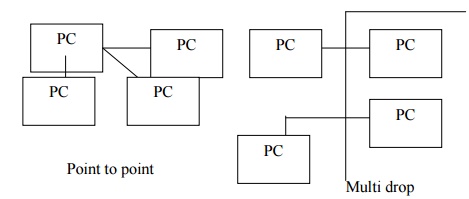
Network Wiring methods;
There are two basic ways by which
three or more nodes can be incorporated in a network. These are point – to – point
and multi drop.
Related Topics