Chapter: Mechanical : Computer Integrated Manufacturing : Computer Aided Design
Geometric modeling
Geometric modeling
Geometric modeling involves the
use of a CAD system to develop a mathematical description of the geometry of an
object. The mathematical description, called a geometric model is contained in
computer memory. These operations include creating new geometric models from
basic building blocks available in the system. Geometric modeling is a branch
of applied mathematics and computational geometry that studies methods and
algorithms for the mathematical description of shapes.
The shapes studied in geometric
modeling are mostly two- or three-dimensional, although many of its tools and
principles can be applied to sets of any finite dimension. Today most geometric
modeling is done with computers and for computer-based applications.
Two-dimensional models are important in computer typography and technical
drawing. Three-dimensional models are central to computer-aided design and
manufacturing (CAD/CAM), and widely used in many applied technical fields such
as civil and mechanical engineering, architecture, geology and medical image
processing.
Geometric models are usually
distinguished from procedural and object-oriented models, which define the
shape implicitly by an opaque algorithm that generates its appearance. They are
also contrasted with digital images and volumetric models which represent the
shape as a subset of a fine regular partition of space; and with fractal models
that give an infinitely recursive definition of the shape.
However, these distinctions are
often blurred: for instance, a digital image can be interpreted as a collection
of colored squares; and geometric shapes such as circles are defined by
implicit mathematical equations. Also, a fractal model yields a parametric or
implicit model when its recursive definition is truncated to a finite depth.
Geometric modeling techniques;
These are
various types of geometric models used in CAD,
·
Based on the dimensioning, - Two dimensional
modeling, - Three dimensional modeling.
·
Based on the modeling,
-
Wire frame modeling,
-
Surface modeling,
-
Solid modeling.
2D Vs 3D;
2D models are best utilized for design problems,
such as flat objects and layouts of building.
3D models are capable of modeling an object in
three dimensional according to user instructions.
This is helpful in conceptualizing the object
since in true 3D models can be displayed in various views and form different
angles.
1.
Wire-frame modeling technique in CAD
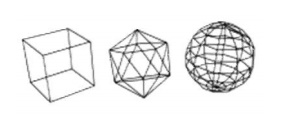
A wire-frame model is a visual
presentation of a three-dimensional (3D) or physical object used in 3D computer
graphics. It is created by specifying each edge of the physical object where
two mathematically continuous smooth surfaces meet, or by connecting an
object's constituent vertices using straight lines or curves. The object is
projected onto a display screen by drawing lines at the location of each edge.
The term wire frame comes from designers using metal wire to represent the
three-dimensional shape of solid objects. 3D wire frame allows to construct and
manipulate solids and solid surfaces. The 3D solid modeling technique
efficiently draws higher quality representations of solids than the
conventional line drawing.
Using a wire-frame model allows
visualization of the underlying design structure of a 3D model. Traditional
two-dimensional views and drawings can be created by appropriate rotation of
the object and selection of hidden line removal via cutting planes. Since
wire-frame renderings are relatively simple and fast to calculate, they are
often used in cases where a high screen frame rate is needed (for instance,
when working with a particularly complex 3D model, or in real-time systems that
model exterior phenomena). When greater graphical detail is desired, surface
textures can be added automatically after completion of the initial rendering
of the wire frame. This allows the designer to quickly review Chan solids or
rotate the object to new desired views without long delays associated with more
realistic rendering.
The wire frame format is also
well suited and widely used in programming tool paths for direct numerical
control (DNC) machine tools. Hand-drawn wire-frame-like illustrations date back
as far as the Italian Renaissance.[1] Wire-frame models were also
used extensively in video games to represent 3D objects during the 1980s and
early 1990s when properly filled 3D objects would have been too complex to
calculate and draw with the computers of the time. Wire-frame models are also
used as the input for computer-aided manufacturing (CAM). There are mainly
three types of 3D CAD models. Wire frame is one of them and it is the most
abstract and least realistic. Other types of 3D CAD models are surface and
solid. This method of modeling consists of only lines, points and curves
defining the edges of an object.
Advantages of Wireframe Modeling;
·
Simple to construct,
·
Designer needs little training.
·
It needs less memory space,
·
It takes less manipulation time,
·
It is best suitable for manipulation as
orthographic, isometric and perspective views.
B-rep – Boundry
representation;
B-rep construction consists of entering all boundary edge for
all surfaces. This is similar or copying an engineering drawing into the
computer, line by line,
surface by surface, with one important qualification. The
lines must be entered and surfaces oriented in such a way that they create
valid volumes.
CSG –
Constructive Solid Geometry;
CSG technique uses Boolean combinations or
primitives solids to build a part. The Boolean operations are addition (+),
subtraction (-), as illustrated in three dimensions.
2. Surface modeling
Surface
modeling is defining an object’s exterior with an infinitesimally thin skin.
This skin is created by lofts,
sweeps, and NURBS curves - i.e. sculptured surfaces with lots of curvature. The
surfaces are either defined by poles or guide curves. A surface is
considered a solid only when it is completely enclosed. It is
used to make technical surfaces
(e.g. air plane wing) or aesthetic surfaces (e.g.
car’s hood).
It was developed for the
aerospace and automotive industries in the late 70s. Rhinoceros 3D and Alias
Studio Tools are examples of a surface modeling programs. It is generally
considered more difficult than solids modeling, but the models are more robust because
the programs aren’t generally feature based. Later changes have to modify the existing
geometry as opposed to just editing the original feature, which is more
difficult but keeps the model from collapsing when one feature interferes with
another.
3. Solid modeling technique in CAD
Solid modeling (or modelling) is
a consistent set of principles for mathematical and computer modeling of
three-dimensional solids. Solid modeling is distinguished from related areas of
geometric modeling and computer graphics by its emphasis on physical fidelity.[1]
Together, the principles of geometric and solid modeling form the foundation of
computer-aided design and in general support the creation, exchange,
visualization, animation, interrogation, and annotation of digital models of
physical objects.
The use of solid modeling
techniques allows for the automation of several difficult engineering
calculations that are carried out as a part of the design process. Simulation,
planning, and verification of processes such as machining and assembly were one
of the main catalysts for the development of solid modeling. More recently, the
range of supported manufacturing applications has been greatly expanded to
include sheet metal manufacturing, injection molding, welding, pipe routing
etc.
Beyond
traditional manufacturing, solid modeling techniques serve as the foundation
for rapid prototyping, digital data archival and reverse engineering by
reconstructing solids from sampled points on physical objects, mechanical
analysis using finite elements, motion planning and NC path verification,
kinematic and dynamic analysis of mechanisms, and so on.
A central problem in all these
applications is the ability to effectively represent and manipulate
three-dimensional geometry in a fashion that is consistent with the physical
behavior of real artifacts. Solid modeling research and development has
effectively addressed many of these issues, and continues to be a central focus
of computer-aided engineering.
Advantages of Solid Modeling;
·
It is complete and unambiguous.
·
Suitable for automated applications like creating
part program without much human involvement.
4.Solids vs. Surface
Modeling;
Computer aided design
(CAD) isn’t like a car in that you can use it pretty well even if
you don’t know how it works. It pays to know what happening ‘under the hood’
when
using CAD. It is important to
know about surface and solids modeling because it does affect the way you
model, and it is important to know if you are switching platforms. It is also
very important to know about for rapid prototyping.
Surfaces
and solids are the underlying math that defines the geometry of the forms
you create. There are three ways to define 3D geometry:
solids, surfaces and wireframes.
Wireframes don’t play much of a role in CAD, but
primarily in digital content creation
(DCC) and gaming. The easiest way
to understand the difference between surface and solids modeling is to think of
a water balloon; the water in the balloon would be solids modeling, while the
latex skin would be surface modeling. Need more of an explanation? No problem.
Solids modeling;
Solids modeling is defining an
object with geometric mass. Solids modeling programs usually create models by
creating a base solid and adding or subtracting from it with subsequent
features. Features such as extrudes, extrude cuts, revolves, radii, chamfers,
etc. Examples of solids modeling programs are Solid works, CATIA, and Pro
Engineer. It was originally developed for machine design, and is used heavily
for engineering with large part assemblies, digital testing and rapid
prototyping.
Surface modeling;
Surface
modeling is defining an object’s exterior with an infinitesimally thin skin.
This skin is created by lofts, sweeps, and NURBS curves - i.e. sculptured surfaces with lots of curvature. The surfaces are either defined by poles or guide curves. A surface is considered a solid only when it is completely enclosed. It is used to make technical surfaces
(e.g. air plane wing) or aesthetic surfaces (e.g.
car’s hood).
It was developed for the aerospace and automotive industries in the late 70s. Rhinoceros 3D and Alias Studio Tools are examples of a surface modeling programs. It is generally considered more difficult than solids modeling, but the models are more robust because the programs aren’t generally feature based. Later changes have to modify the existing geometry as opposed to just editing the original feature, which is more difficult but keeps the model from collapsing when one feature interferes with another.
Related Topics