Chapter: Mechanical : Computer Integrated Manufacturing : Computer Aided Design
Wire-frame modeling technique in CAD
Wire-frame modeling technique in CAD
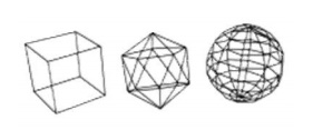
A wire-frame model is a visual presentation of a three-dimensional (3D) or physical object used in 3D computer graphics. It is created by specifying each edge of the physical object where two mathematically continuous smooth surfaces meet, or by connecting an object's constituent vertices using straight lines or curves. The object is projected onto a display screen by drawing lines at the location of each edge. The term wire frame comes from designers using metal wire to represent the three-dimensional shape of solid objects. 3D wire frame allows to construct and manipulate solids and solid surfaces. The 3D solid modeling technique efficiently draws higher quality representations of solids than the conventional line drawing.
Using a wire-frame model allows visualization of the underlying design structure of a 3D model. Traditional two-dimensional views and drawings can be created by appropriate rotation of the object and selection of hidden line removal via cutting planes. Since wire-frame renderings are relatively simple and fast to calculate, they are often used in cases where a high screen frame rate is needed (for instance, when working with a particularly complex 3D model, or in real-time systems that model exterior phenomena). When greater graphical detail is desired, surface textures can be added automatically after completion of the initial rendering of the wire frame. This allows the designer to quickly review Chan solids or rotate the object to new desired views without long delays associated with more realistic rendering.
The wire frame format is also well suited and widely used in programming tool paths for direct numerical control (DNC) machine tools. Hand-drawn wire-frame-like illustrations date back as far as the Italian Renaissance.[1] Wire-frame models were also used extensively in video games to represent 3D objects during the 1980s and early 1990s when properly filled 3D objects would have been too complex to calculate and draw with the computers of the time. Wire-frame models are also used as the input for computer-aided manufacturing (CAM). There are mainly three types of 3D CAD models. Wire frame is one of them and it is the most abstract and least realistic. Other types of 3D CAD models are surface and solid. This method of modeling consists of only lines, points and curves defining the edges of an object.
Advantages of Wireframe Modeling;
· Simple to construct,
· Designer needs little training.
· It needs less memory space,
· It takes less manipulation time,
· It is best suitable for manipulation as orthographic, isometric and perspective views.
B-rep – Boundry representation;
B-rep construction consists of entering all boundary edge for all surfaces. This is similar or copying an engineering drawing into the computer, line by line,
surface by surface, with one important qualification. The lines must be entered and surfaces oriented in such a way that they create valid volumes.
CSG – Constructive Solid Geometry;
CSG technique uses Boolean combinations or primitives solids to build a part. The Boolean operations are addition (+), subtraction (-), as illustrated in three dimensions.
Related Topics