Chapter: Embedded and Real Time Systems : Introduction to Embedded Computing
Formalisms for System Design
FORMALISMS
FOR SYSTEM DESIGN:
Visual
language that can be used to capture all these design tasks: the Unified
Modeling Language (UML). UML was designed to be useful at many levels of
abstraction in the design process. UML is useful because it encourages
design by successive refinement and progressively adding detail to the design,
rather than rethinking the design at each new level of abstraction.
UML is an
object-oriented
modeling language. We will see precisely what we mean by an object in just a
moment, but object-oriented design emphasizes two concepts of importance:
It encourages the design to be described as a
number of interacting objects, rather than a few large monolithic blocks of
code.
At least some of those object will correspond to
real pieces of software or hardware in the system. We can also use UML to model
the outside world that interacts with our system, in which case the objects may
correspond to people or other machines. It is sometimes important to implement
something we think of at a high level as a single object using several distinct
pieces of code or to otherwise break up the object correspondence in the
implementation However, thinking of the design in terms of actual objects helps
us understand the natural structure of the system. Object-oriented (often
abbreviated OO) specification can be seen in two complementary ways:
Object-oriented specification allows a system to be
described in a way that closely models real-world objects and their
interactions.
Object-oriented specification provides a basic set
of primitives that can be used to describe systems with particular attributes,
irrespective of the relationships of those systems’ components to real-world
objects.
Both
views are useful. At a minimum, object-oriented specification is a set of
linguistic mechanisms. In many cases, it is useful to describe a system in
terms of real-world analogs. However, performance, cost, and so on may dictate
that we change the specification to be different in some ways from the
real-world elements we are trying to model and implement. In this case, the
object-oriented specification mechanisms are still useful.
A specification
language may not be executable. But both object-oriented specification and
programming languages provide similar basic methods for structuring large
systems.
Unified Modeling Language (UML)—the
acronym is the name is a large language, and
covering all of it is beyond the scope of this book. In this section, we
introduce only a few basic concepts. In later chapters, as we need a few more
UML concepts, we introduce them to the basic modeling elements introduced here.
Because
UML is so rich, there are many graphical elements in a UML diagram. It is
important to be careful to use the correct drawing to describe something for
instance; UML distinguishes between arrows with open and filled-in arrowheads,
and solid and broken lines. As you become more familiar with the language, uses
of the graphical primitives will become more natural to you.
We also
won’t take a strict object-oriented approach. We may not always use objects for
certain elements of a design—in some cases, such as when taking particular
aspects of the implementation into account, it may make sense to use another
design style. However, object-oriented design is widely applicable, and no
designer can consider himself or herself design literate without understanding
it.
1.
Structural Description:
By structural description, we mean the
basic components of the system; we will learn how to describe how these
components act in the next section. The principal component of an
object-oriented design is, naturally enough, the object. An object
includes a set of attributes that define its internal state.
When implemented in a programming language, these
attributes usually become variables or constants held in a data structure. In
some cases, we will add the type of the attribute after the attribute name for
clarity, but we do not always have to specify a type for an attribute. An
object describing a display (such as a CRT screen) is shown in UML notation in
Figure 1.8 a).
The text in the folded-corner page icon is a note;
it does not correspond to an object in the system and only serves as a comment.
The attribute is, in this case, an array of pixels that holds the contents of
the display. The object is identified in two ways: It has a unique name, and it
is a member of a class. The name is underlined to show that this is a
description of an object and not of a class.
A class is a form of type definition—all objects
derived from the same class have the same characteristics, although their
attributes may have different values. A class defines the attributes that an
object may have. It also defines the operations that determine how the
object interacts with the rest of the world. In a programming language, the
operations would become pieces of code used to manipulate the object.
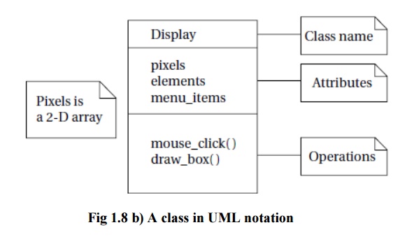
The UML description of the Display class is shown in Figure 1.8 b). The class has the name
that we saw used in the d1 object
since d1 is an instance of class Display.
The Display
class defines the pixels attribute
seen in the object; remember that when we instantiate the class an object, that
object will have its own memory so that different objects of the same class
have their own values for the attributes. Other classes can examine and modify
class attributes; if we have to do something more complex than use the attribute
directly, we define a behavior to perform that function.
A class defines both the interface for a
particular type of object and that object’s implementation. When we
use an object, we do not directly manipulate its attributes—we can only
read or modify the object’s state through the operations that define the
interface to the object.
As long as we do not change the behavior of the
object seen at the interface, we can change the implementation as much as we
want. This lets us improve the system by, for example, speeding up an operation
or reducing the amount of memory required without requiring changes to anything
else that uses the object.


We need to make the object’s interface general
enough so that we can make full use of its capabilities. However, excessive
generality often makes the object large and slow. Big, complex interfaces also
make the class definition difficult for designers to understand and use
properly.
There are
several types of relationships that can exist between objects and classes:
■Association
occurs between objects that communicate with each other but have no ownership
relationship between them.
■ Aggregation
describes a complex object made of smaller objects.
■Composition
is a type of aggregation in which the owner does not allow access to the
component objects.
■ Generalization
allows us to define one class in terms of another.
2.
Behavioral Description:
We have to specify the behavior of the system as
well as its structure. One way to specify the behavior of an operation is a state
machine.
These state machines will not rely on the operation
of a clock, as in hardware; rather, changes from one state to another are
triggered by the occurrence of events.


An event
is some type of action. The event may originate outside the system, such as a
user pressing a button. It may also originate inside, such as when one routine
finishes its computation and passes the result on to another routine.We will
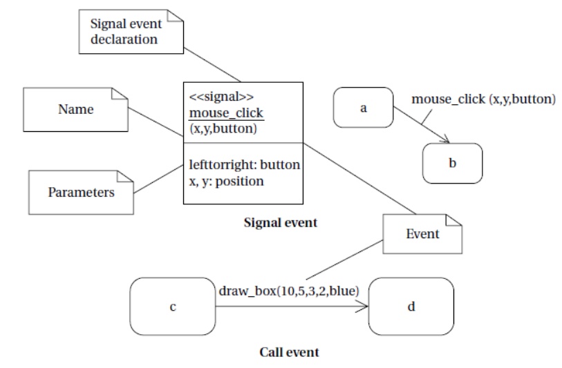
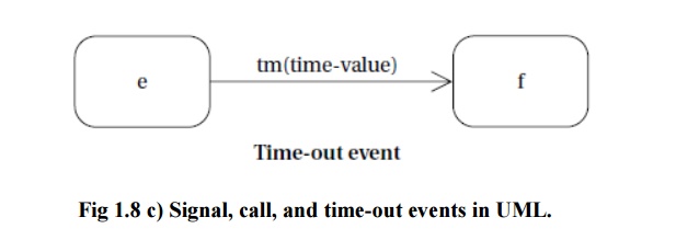
concentrate on the following three types of events defined by UML, as
illustrated in Figure 1.8 c):
A signal is an asynchronous
occurrence. It is defined in UML by an object that is labeled as a <<signal>>. The object in the
diagram serves as a declaration of the event’s existence. Because it is an
object, a signal may have parameters that are passed to the signal’s receiver.
A call
event follows the model of a procedure call in a programming language.
■A time-out
event causes the machine to leave a state after a certain amount of
time. The label tm(time-value) on the
edge gives the amount of time after which the transition occurs. A time-out is
generally implemented with an
external timer. This notation simplifies the specification and allows us to
defer implementation details about the time-out mechanism.
Related Topics