Chapter: Embedded and Real Time Systems : Introduction to Embedded Computing
Design Example: Model Train Controller
DESIGN
EXAMPLE: MODEL TRAIN CONTROLLER
In order
to learn how to use UML to model systems, we will specify a simple system, a
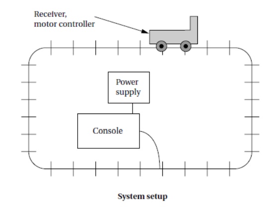
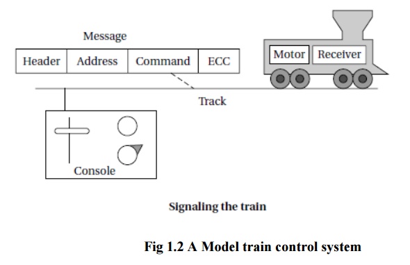
model train controller, which is illustrated in Figure 1.2.The user sends
messages to the train with a control box attached to the tracks.
The
control box may have familiar controls such as a throttle, emergency stop
button, and so on. Since the train receives its electrical power from the two
rails of the track, the control box can send signals to the train over the
tracks by modulating the power supply voltage. As shown in the figure, the
control panel sends packets over the tracks to the receiver on the train.
The train
includes analog electronics to sense the bits being transmitted and a control
system to set the train motor’s speed and direction based on those commands.
Each
packet includes an address so that the console can control several trains on
the same track; the packet also includes an error correction code (ECC) to
guard against transmission errors. This is a one-way communication system the
model train cannot send commands back to the user.
We start
by analyzing the requirements for the train control system.We will base our
system on a real standard developed for model trains.We then develop two
specifications: a simple, high-level specification and then a more detailed
specification.
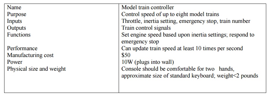
Requirements
Before we
can create a system specification, we have to understand the requirements.
Here is a
basic set of requirements for the system:
The
console shall be able to control up to eight trains on a single track.
The speed
of each train shall be controllable by a throttle to at least 63 different
levels in each direction (forward and reverse).
There
shall be an inertia control that shall allow the user to adjust the
responsiveness of the train to commanded changes in speed. Higher inertia means
that the train responds more slowly to a change in the throttle, simulating the
inertia of a large train. The inertia control will provide at least eight
different levels.
There
shall be an emergency stop button.
An error
detection scheme will be used to transmit messages.
We can
put the requirements into chart format:
We will develop
our system using a widely used standard for model train control. We could
develop our own train control system from scratch, but basing our system upon a
standard has several advantages in this case: It reduces the amount of work we
have to do and it allows us to use a wide variety of existing trains and other
pieces of equipment.
DCC
The Digital Command Control (DCC) was
created by the National Model Railroad Association to support interoperable
digitally-controlled model trains.
Hobbyists
started building homebrew digital control systems in the 1970s and Marklin
developed its own digital control system in the 1980s. DCC was created to
provide a standard that could be built by any manufacturer so that hobbyists
could mix and match components from multiple vendors.
The DCC
standard is given in two documents:
Standard
S-9.1, the DCC Electrical Standard, defines how bits are encoded on the rails
for transmission.
Standard
S-9.2, the DCC Communication Standard, defines the packets that carry
information.
Any
DCC-conforming device must meet these specifications. DCC also provides several
recommended practices. These are not strictly required but they provide some
hints to manufacturers and users as to how to best use DCC.
The DCC
standard does not specify many aspects of a DCC train system. It doesn’t define
the control panel, the type of microprocessor used, the programming language to
be used, or many other aspects of a real model train system.
The
standard concentrates on those aspects of system design that are necessary for
interoperability. Over standardization, or specifying elements that do not
really need to be standardized, only makes the standard less attractive and
harder to implement.
The
Electrical Standard deals with voltages and currents on the track. While the
electrical engineering aspects of this part of the specification are beyond the
scope of the book, we will briefly discuss the data encoding here.
The
standard must be carefully designed because the main function of the track is
to carry power to the locomotives. The signal encoding system should not
interfere with power transmission either to DCC or non-DCC locomotives. A key
requirement is that the data signal should not change the DC value of the
rails.
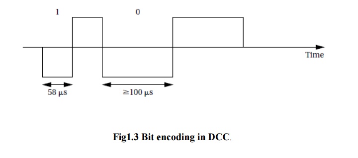
The data
signal swings between two voltages around the power supply voltage. As shown in
Figure 1.3, bits are encoded in the time between transitions, not by voltage
levels. A 0 is at least 100 ms while a 1 is nominally 58ms.
The
durations of the high (above nominal voltage) and low (below nominal voltage)
parts of a bit are equal to keep the DC value constant. The specification also
gives the allowable variations in bit times that a conforming DCC receiver must
be able to tolerate.
The
standard also describes other electrical properties of the system, such as
allowable transition times for signals.
The DCC
Communication Standard describes how bits are combined into packets and the
meaning of some important packets.
Some
packet types are left undefined in the standard but typical uses are given in
Recommended Practices documents. We can write the basic packet format as a
regular expression:
PSA (sD)
+ E ........ ( 1.1)
In this
regular expression:
P is the preamble, which is a sequence
of at least 10 1 bits. The command station should send at least 14 of these 1 bits, some of which may
be corrupted during transmission.
S is the packet start bit. It is a
0 bit.
A is an address data byte that
gives the address of the unit, with the most significant bit of the address transmitted first. An address is eight
bits long. The addresses 00000000, 11111110, and 11111111 are reserved.
s is the data byte start bit,
which, like the packet start bit, is a 0.
D is the data byte, which includes
eight bits. A data byte may contain an address, instruction, data, or error correction information.
E is a packet end bit, which is a 1
bit.
A packet
includes one or more data byte start bit/data byte combinations. Note that the
address data byte is a specific type of data byte.
A baseline
packet is the minimum packet that must be accepted by all DCC
implementations. More complex packets are given in a Recommended Practice
document.
A
baseline packet has three data bytes: an address data byte that gives the
intended receiver of the packet; the instruction data byte provides a basic
instruction; and an error correction data byte is used to detect and correct
transmission errors.
The
instruction data byte carries several pieces of information. Bits 0–3 provide a
4-bit speed value. Bit 4 has an additional speed bit, which is interpreted as
the least significant speed bit. Bit 5 gives direction, with 1 for forward and
0 for reverse. Bits 7–8 are set at 01 to indicate that this instruction
provides speed and direction.
The error
correction data byte is the bitwise exclusive OR of the address and instruction
data bytes.
The
standard says that the command unit should send packets frequently since a
packet may be corrupted. Packets should be separated by at least 5 ms.
Conceptual
Specification
Digital
Command Control specifies some important aspects of the system, particularly
those that allow equipment to interoperate. But DCC deliberately does not
specify everything about a model train control system. We need to round out our
specification with details that complement the DCC spec.
A
conceptual specification allows us to understand the system a little better. We
will use the experience gained by writing the conceptual specification to help
us write a detailed specification to be given to a system architect. This
specification does not correspond to what any commercial DCC controllers do,
but it is simple enough to allow us to cover some basic concepts in system
design.
A train
control system turns commands into packets. A command comes
from the command unit while a packet is transmitted over the rails.
Commands
and packets may not be generated in a 1-to-1 ratio. In fact, the DCC standard
says that command units should resend packets in case a packet is dropped
during transmission.
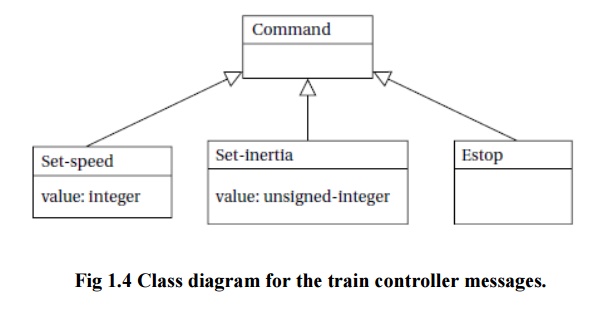
We now
need to model the train control system itself. There are clearly two major
subsystems: the command unit and the train-board component as shown in Figure
1.4. Each of these subsystems has its own internal structure.
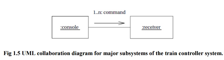
The basic
relationship between them is illustrated in Figure 1.5. This figure shows a UML
collaboration
diagram; we could have used another type of figure, such as a class or
object diagram, but we wanted to emphasize the transmit/receive
relationship between these major subsystems. The command unit and receiver are
each represented by objects; the command unit sends a sequence of packets to
the train’s receiver, as illustrated by the arrow.
The
notation on the arrow provides both the type of message sent and its sequence
in a flow of messages; since the console sends all the messages, we have
numbered the arrow’s messages as
1..n. Those messages are of course
carried over the track.
Since the
track is not a computer component and is purely passive, it does not appear in
the diagram. However, it would be perfectly legitimate to model the track in
the collaboration diagram, and in some situations it may be wise to model such
nontraditional components in the specification diagrams. For example, if we are
worried about what happens when the track breaks, modeling the tracks would
help us identify failure modes and possible recovery mechanisms.
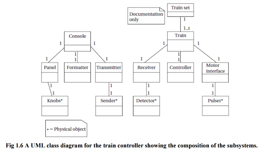
Let’s
break down the command unit and receiver into their major components. The
console needs to perform three functions: read the state of the front panel on
the command unit, format messages, and transmit messages. The train receiver
must also perform three major functions: receive the message, interpret the
message (taking into account the current speed, inertia setting, etc.),and
actually control the motor. In this case, let’s use a class diagram to
represent the design; we could also use an object diagram if we wished. The UML
class diagram is shown in Figure 1.6. It shows the console class using three
classes, one for each of its major components. These classes must define some
behaviors, but for the moment we will concentrate on the basic characteristics
of these classes:
The Console class describes the command
unit’s front panel, which contains the analog knobs and hardware to interface
to the digital parts of the system.
The Formatter class includes behaviors that
know how to read the panel knobs and creates a bit stream for the required
message.
The Transmitter class interfaces to analog
electronics to send the message along the track.
There
will be one instance of the Console
class and one instance of each of the component classes, as shown by the
numeric values at each end of the relationship links. We have also shown some
special classes that represent analog components, ending the name of each with
an asterisk:
Knobs* describes the actual analog
knobs, buttons, and levers on the control panel.
Sender* describes the analog
electronics that send bits along the track.
Likewise,
the Train makes use of three other classes that define its components:
The Receiver class knows how to turn the
analog signals on the track into digital form.
The Controller class includes behaviors that
interpret the commands and figures out how to control the motor.
The Motor interface class defines how to
generate the analog signals required to control the motor. We define two
classes to represent analog components:
Detector* detects analog signals on the
track and converts them into digital form.
Pulser* turns digital commands into the
analog signals required to control the motor speed.
We have
also defined a special class, Train set,
to help us remember that the system can handle multiple trains. The values on
the relationship edge show that one train set can have t trains. We would not actually implement the train set class, but
it does serve as useful documentation of the existence of multiple receivers.
Related Topics