Chapter: Embedded and Real Time Systems : Introduction to Embedded Computing
ARM Procssor
ARM
PROCSSOR:
In this section, we concentrate on the ARM
processor. ARM is actually a family of RISC architectures that have been
developed over many years.
ARM does not manufacture its own VLSI devices;
rather, it licenses its architecture to companies who either manufacture the
CPU itself or integrate the ARM processor into a larger system.
The textual description of instructions, as opposed
to their binary representation, is called an assembly language.
ARM instructions are written one per line, starting
after the first column. Comments begin with a semicolon and continue to the end
of the line. A label, which gives a name to a memory location, comes at the
beginning of the line, starting in the first column. Here is an example:
LDR r0,
[r8]; a comment
label ADD
r4,r0,r1
1.
Processor and Memory Organization:
Different versions of the ARM architecture are
identified by different numbers. ARM7 is a von Neumann architecture machine,
while ARM9 uses Harvard architecture.
However, this difference is invisible to the
assembly language programmer, except for possible performance differences.
The ARM
architecture supports two basic types of data:
The standard ARM word is 32 bits long.
The word may be divided into four 8-bit bytes.
ARM7 allows addresses up to 32 bits long. An
address refers to a byte, not a word. Therefore, the word 0 in the ARM address
space is at location 0, the word 1 is at 4, the word 2 is at 8,and so on. (As a
result, the PC is incremented by 4 in the absence of a branch.)
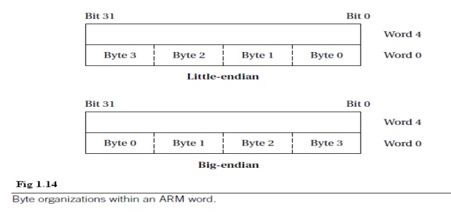
The ARM processor can be configured at power-up to
address the bytes in a word in either little-endian mode (with the
lowest-order byte residing in the low-order bits of the word) or
big-endian mode (the lowest-order byte stored in the highest bits of
the word), as illustrated in Figure 1.14 [Coh81]. General
purpose computers have sophisticated instruction sets.
Some of this sophistication is required simply to provide the functionality of a general computer, while other aspects of instruction sets may be provided to increase performance, reduce code size, or otherwise improve program characteristics.
2. Data
Operations:
Arithmetic and logical operations in C are
performed in variables. Variables are implemented as memory locations.
Therefore, to be able to write instructions to perform C expressions and
assignments, we must consider both arithmetic and logical instructions as well
as instructions for reading and writing memory.
Figure 1.15 shows a sample fragment of C code with
data declarations and several assignment statements. The variables a, b,
c, x, y, and z all become data locations in memory.
In most cases data are kept relatively separate from instructions in the
program’s memory image.
In the ARM processor, arithmetic and logical
operations cannot be performed directly on memory locations. While some
processors allow such operations to directly reference main memory, ARM is a load-store
architecture—data operands must first be loaded into the CPU and then
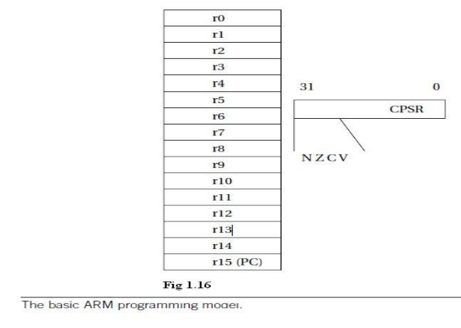
stored back to main memory to save the results. Figure 2.8 shows the registers
in the basic ARM programming model. ARM has 16 general-purpose registers, r0
through r15. Except for r15, they are identical—any operation that can be done
on one of them can be done on the other one also.
The r15 register has the same capabilities as the
other registers, but it is also used as the program counter. The program
counter should of course not be overwritten for use in data operations.
However, giving the PC the properties of a general-purpose register allows the
program counter value to be used as an operand in computations, which can make
certain programming tasks easier. The other important basic register in the
programming model is the current program status register (CPSR).
This register is set automatically during every
arithmetic, logical, or shifting operation. The top four bits of the CPSR hold
the following useful information about the results of that arithmetic/logical
operation:
The negative (N) bit is set when the result is
negative in two’s-complement arithmetic.
The zero (Z) bit is set when every bit of the
result is zero.
The carry (C) bit is set when there is a carry out
of the operation.
The overflow(V) bit is set when an arithmetic
operation results in an overflow.
int a, b,
c, x, y, z; x = (a+b)-c; y=a*(b+c);
z=(a
<< 2) | (b & 15);
Figs 1.15
A C fragment with data operations.
These bits can be used to check easily the results
of an arithmetic operation. However, if a chain of arithmetic or logical
operations is performed and the intermediate states of the CPSR bits are
important, then they must be checked at each step since the next operation
changes the CPSR values.
The basic form of a data instruction is simple:
ADD
r0,r1,r2
This instruction sets register r0 to the sum of the
values stored in r1 and r2. In addition to specifying registers as sources for
operands, instructions may also provide immediate operands, which encode a
constant value directly in the instruction. For example,
ADD
r0,r1,#2 sets r0 to r1+2.
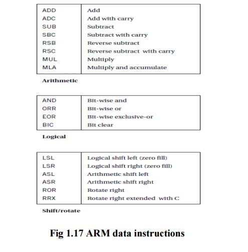
The major data operations are summarized in Figure
1.17. The arithmetic operations perform addition and subtraction; the
with-carry versions include the current value of the carry bit in the
computation.
RSB performs a subtraction with the order of the
two operands reversed, so that RSB r0, r1, r2 sets r0 to be r2_r1.The bit-wise
logical operations perform logical AND, OR, and XOR operations (the exclusive
or is called EOR).
The BIC instruction stands for bit clear: BIC r0,
r1, r2 sets r0 to r1 and not r2. This instruction uses the second source
operand as a mask: Where a bit in the mask is 1, the corresponding bit in the
first source operand is cleared.
The MUL instruction multiplies two values, but with
some restrictions: No operand may be an immediate, and the two source operands
must be different registers.
The MLA instruction performs a multiply-accumulate
operation, particularly useful in matrix operations and signal processing. The
instruction
MLA r0,
r1, r2, r3
Sets r0
to the value r1*r2+r3.
The shift operations are not separate instructions
rather; shifts can be applied to arithmetic and logical instructions. The shift
modifier is always applied to the second source operand.
A left shift moves bits up toward the
most-significant bits, while a right shift moves bits down to the
least-significant bit in the word.
The LSL and LSR modifiers perform left and right
logical shifts, filling the least-significant bits of the operand with zeroes.
The arithmetic shift left is equivalent to an LSL, but the ASR copies the sign
bit—if the sign is 0, a 0 is copied, while if the sign is 1, a 1 is copied.
The rotate modifiers always rotate right, moving
the bits that fall off the least-significant bit up to the most-significant bit
in the word. The RRX modifier performs a 33-bit rotate, with the CPSR’s C bit
being inserted above the sign bit of the word; this allows the carry bit to be
included in the rotation.
Related Topics