Chapter: Automation, Production Systems, and Computer Integrated Manufacturing : Numerical Control
Engineering Analysis of Numerical Control(NC) Positioning Systems
ENGINEERING ANALYSIS
OF NC
POSITIONING SYSTEMS
The
NCpositioning system converts the coordinate axis values in the NC part program
into relative positions of the tool and workpart during processing. Let us
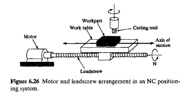
consider the simple positioning system shown in Figure 6.26. The system
consists of a cutting tool and a worktable on which a workpart is fixtured. The
table is designed to move the part relative to the tool. The worktable moves
linearly b)' means of a rotating leadscrew, which is driven by a stepping motor
or servomotor. For simplicity, we show only one axis in our sketch. To provide .~.y capability: the system shown would
be piggybacked on top of a second axis per, pendicular to the first. The
leadscrew bas a certain pitchp (in/thread, mm/thread). Thus, the table mows a
distance equal to the pitch for each revolution. The velocity of the worktable,
which corresponds to the feed rate in a machining operation, is determined by
the rotational speed 01 the leadscrew,
There are two types of positioning systems used
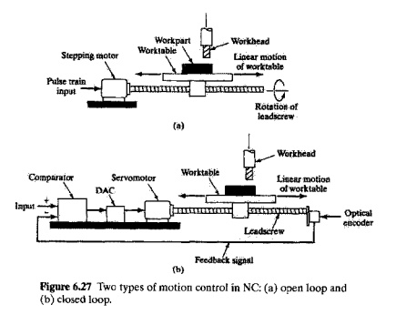
in NC systems: (a) open loop and (b) closed loop, as shown in Figure
6.27. An open-loop system operates without verifying that the actual
position achieved in the move is the same as the desired position. A closed loop control system uses feedback
measurements to confirm that the final position of the worktable is the location specified in the program. Open loop
systems cost less than closedloop systems and are appropriate when the force
resisting the actuating motion is minimal. Closed loop systems are normally
specified for machines that perform continuous path operations such as milling
or turning, in which there are significant forces resisting the forward motion
of the Cuting tool.
Open Loop
Postioning Systems
An
openloop positioning system typically uses a stepping motor to rotate the
leadscrew A stepping motor is driven by a series of electrical pulses, which
are generated by the MCU in an NC system. Each pulse causes the motor to rotate
a fraction of one revolution. called the step angle. The possible step angles
must be consistent with the following relationship:

where ct = step angle (degrees), and n, = the number of step angles for the
motor, which must be an integer. The angle through which the motor shaft
rotates is given by

where Am = angle of
motor shaft rotation (degrees), np == number of pulses received by the
motor. and ct = step angle (degrees/pulse). The
motor shaft is generally connected to the leadscrew through a gear box, which
reduces the angular rotation of the leadscrew. The angle of the leadserew
rotation must take the gear ratio into account as follows'

where A == angle of
leadscrew rotation (degrees), and r g = gear
ratio, defined as the number of turns of the molor for each single turn of the
leadserew. That is,

where x == xaxis
position relative to the starting position (mm, inch), p = pitch of the leadscrew (nun/rev,
in/rev).and Aj360 = number of Ieadscrew revolutions,
The number of pulses required to achieve a specified .rposition increment in a
pointtopoint system can be found by combining the two preceding equations as
follows:

where the
second expression on the righthand side is obtained by substituting n, for 360/ a, which is obtained by rearranging Eq. (6.10).
Control
pulses are transmitted from the pulse generator at a certain frequency, which
drives the worktable at a corresponding velocity or feed rate in the direction
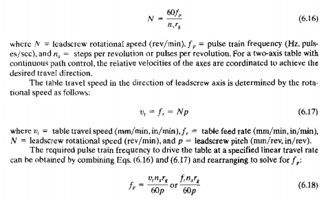
of the leadscrew axis. The rotational speed of the leadscrew depends on the
frequency of the pulse train as follows:
EXAMPLE 6.7 NC
Open-Loop Positioning
The
worktable of a positioning system is driven by a leadserew whose pitch == 6.0 mm. The leadscrew is
connected to the output shaft of a stepping motor through a gearbox whose ratio
ts S: 1 (5 turns of the motor to one turn of the leadscrew). The stepping motor
has 48 step angles. The table must move a distance of 250 mm from its present
position at a linear velocity '" 500 mm/min Determine (a) how many pulses
are required to move the table the specified distance and (b) the required
motor speed and pulse rate to aehieve the desired table velocity,
Solution: (a) Rearranging Eq. (6.14) to
find the teadscrew rotation angle A
corresponding to a distance x = 250 mm,

Closed Loop Positioning
Systems
A
closed-loop NC system, illustrated in Figure 6.27(h). uses servomotors and
feedback measurements to ensure that the worktable is moved to the desired
position. A common feedback sensor used for NC (and also for industrial robots)
is the optical encoder, shown in Figure 6.28. An optical encoder consists of a
light source and a photodetector on either side of a disk. The disk contains
slots uniformly spaced around the outside of its face. These slots allow the
light source to shine through and energize the photodetector. The disk is
connected, either directly or through a gear box, to a rotating shaft whose
angular position and velocity are to be measured. As the shaft rotates, the
slots cause the light source to be seen by the photocell as a series of
flashes. The flashes are converted into an equal number of electrical pulses.
By counting the pulses and computing the frequency of the pulse train,
worktable position and velocity can be determined.
The
equations that define the operation of a closedloop NC positioning system are
similar to those for an openloop system. In the basic optical encoder, the
angle between slots in the disk must satisfy the following requirement:
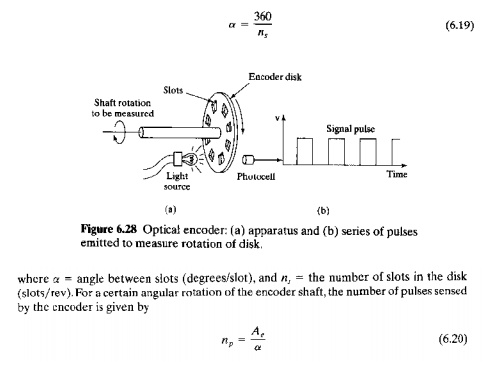
where np = pulse count emitted by the encoder, Ae = angle of rotation of the encoder
shan (degrees), and a = angle between slots, which
converts to degrees per pulse. The pulse count can he used to determine the
linear xaxis position of the
worktable by factoring in the leadscrew pitch and the gear reduction between
the encoder shaft and the leadscrew. Thus,

where np and n, are defined above,p =
leadscrew pitch (mm/rev, in/rev), and r
ge = gear reduction between the
encoder and the Ieadscrew, defined as the number of turns of the encoder shaft
for each single turn of the leadscrew, That is,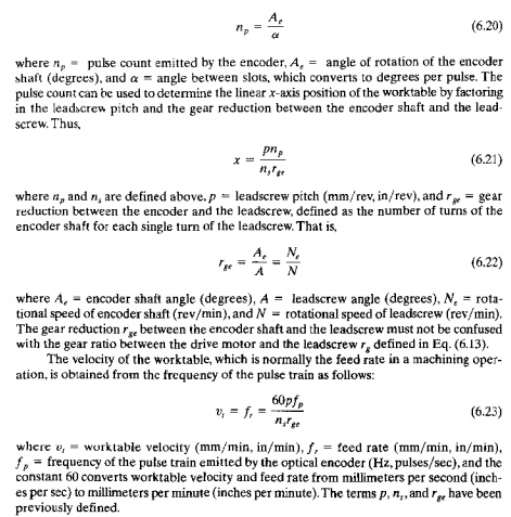
The pulse
train generated by the encoder is compared with the coordinate position and
feed rate specified in the part program, and the difference is used by the MCV to drive
a servomotor, which in tum drives the worktable. A digitaltoanalog converter
(Section 5.4) converts the digital signals used by the MeV into a continuous analog current
that powers the drive motor. Closedloop NC systems of the type described here
are appropriate when a reactionary force resists the movement of the table.
Metal cutting machine tools that perform continuous path cutting operations,
such as milling and turning, fall into this category.
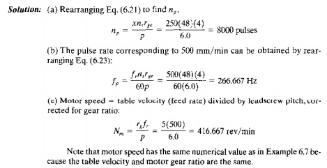
EXAMPLE 6,8 NC ClosedLoop PositioninA
An NC
worktable operates by closedloop positioning. The system consists of a
servomotor, leadscrew, and optical encoder. The leadscrew has a pitch = 6.0 rom
and is
coupled to the motor shaft with a gear ratio of 5: I (5 turns of the drive
motor for each turn of the leadscrcw). The optical encoder generates 48
pulses/rev of its output shaft. The encoder output shaft is coupled to the
Ieadscrew with a 4: 1 reduction (4 turns of the encoder shaft for each turn of
the leadscrew). The table has been programmed to move a distance of 250 mm at a
feed rate = 500
mm/min. Determine (a] how many pulses should be received by the control system
to verify that the table has moved exactly 250 mm, (b) the pulse rate of the
encoder, and (c) the drive motor speed that correspond to the specified feed
rate.
Precision in NC Positioning
For
accurate machining or other processing performed by an NC system, the
positioning system must possess a high degree of precision. Three measures of
precision can be defined for an NC positioning system: (I) control resolution.
(2) accuracy, and (3) repeatability.
These
terms are most readily explained by considering a single axis of the
positioning system, as depicted in Figure 6.29. Control resolution refers to
the control system's ability to
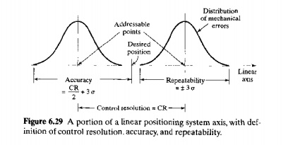
divide
the total range of the axis movement into closely spaced points that can be
distinguished bythe Men Control resolution is defined as the distance separating two
adjacent addressable points in the axis movement. Addressable points are locations along the axis to which the
worktable can be specifically directed to go. It is desirable for control
resolution to be as small as possible. This depends on limitations imposed by:
(1) the electromechanical components of the positioning system and/or (2) the
number of bits used by the controller to define the axis coordinate location.
A number
of electromechanical factors affect control resolution, including: leadscrew
pitch, gear ratio in the drive system, and the step angle in a stepping motor
for an openloop system or the angle between slots in an encoder disk for a
closedloop system. For an openloop positioning system driven by a stepper
motor, these factors can be combined into an expression that defines control
resolution as follows:

A
desirable criterion is for CR2 <= CR1, meaning that the
electromechanical system is the bmiting factor that determines control
resolution. The bit storage capacity of a modem computer controller is
sufficient to satisfy this criterion except in unusual situations. Resolutions
of 0.0025 mm (0,0001 in) are within the current state of NC technology.
The
capability of a positioning system to move the worktable to the exact location
defined by a given addressable point is limited by mechanical errors that are
due to various imperfections in the mechanical system. These imperfections
include play between the leadscrew and the worktable, backlash in the gears,
and deflection of machine components.
We assume
that the mechanical errors form an unbiased normal statistical distribution
about tle control point whose mean IJ. = D. We further assume that the
standard deviation IT of the distribution is constant
over the range of the axis under consideration. Given these assumptions,
then nearly all of the mechanical errors (99.74%) are contained within ±3r:r of
the control point. This is pictured in figure 1i.29for a portion of the axis range
that in
cludes two control
points.
Let us
now make use of these definitions of control resolution and mechanical error
distribution to define accuracy and repeatability of a positioning system.
Accuracy is defined under 'Worst case conditions in which the desired target
point lies in the middle between two adjacent addressable points. Since the
table can only be moved to one or the other of the addressable points, there
will be an error in the final position of the worktable. This is the maximum
possible positioning error, because if the target were closer to either one of
the addressable points, then the table would be moved to the closer control
point and the error would be smaller. It is appropriate to define accuracy
under this worst case scenario. The accuracy
of any given axis of a positioning system is the maximum possible error that
can occur between the desired target point and the actual position taken by the
system'. in equation form,

where CR = control resolution (mm,in), and o = standard
deviation of the error distribution. Accuracies in machine tools are generally
expressed for a certain range of table travel.tor example.Lo.Ot mm for 250mm
(±OJlOO4 in. for 10 in) of table travel
Repeatability
refers to the capability of the positioning system to return to a given addressable
point that has been previously programmed. This capability can be measured in
terms of the location errors encountered when the system attempts to position
itself at the addressable point. Location errors are a manifestation of the
mechanical errors of the positioning system, which follow a normal
distribution, as assumed previously. Thus, the T{,peatability
of any
given axis of a positioning system is ±3 standard deviations of the mechanical
error distribution associated with the axis. This can be written:

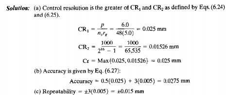
EXAMPLE 6.9 Control Resolution, Accuraq, and Repeatability in NC
Suppose
the mechanical inaccuracies in the openloop positioning system of Example 6.7
are described by a norma! distribution with standard deviation if == 0.005 mm.
The range of the worktable axis is ] 000 mm, and there are 16 bits in th~
binary register used by the digital controller to store the programmed
positron. Other relevant parameters from Example 6.7 are: pitch p = 6.0 mm, gear ratio between motor
shaft and leadscrew r8 = 'i.n, and number of step angles
in the stepping motor ns = 48. Determine (a) the control
resolution. (h) the accuracy. and (c) the repeatability for the positioning
system.
Related Topics