Chapter: Automation, Production Systems, and Computer Integrated Manufacturing : Numerical Control
Computer Assisted Part Programming
Computer Assisted Part Programming
Manual
part programming can be time consuming, tedious. and subject to errors for
parts possessing complex geometries or requiring many machining operations.In
these cases, and even for simpler jobs, it is advantageous to use
computer-assisted part programming.A num ber of NC part programming language
systems have been developed to accomplish many of the calculations that the
programmer would otherwise have to do. This saves time and resuits in a
more-accurate and efficient part program. In computer-assisted part programming.
the various tasks are divided between the human part programmer and the
computer.
In
computer-assisted part programming, the machining instructions are written in
English_like statements that are subsequently translated by the computer into
the low-level machine code that can be interpreted and executed by the machine
tool controller When using one of the part programming languages. the two main
tasks of the programmer are: (1) defining the geometry of the workpart and (2)
specifying the tool path and operation-sequence
Defining
the Part Geometry. No matter how complicated the workpart may appear,
it is composed of basic geometric elements and mathematically defined surfaces.
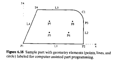
Consider our sample part in Figure 6.18. Although its appearance is somewhat
irregular, the outline of the part consists of intersecting straight lines and
a partial circle. The hole locations in the part can be defined in terms of the
.r. and ycoordinates of their centers. Nearly any component that can be conceived
by a designer can be described by points, straight Jines, planes, circles,
cylinders, and other mathematically defined surfaces. It is the part pro
grammer's
task to identify and enumerate the geometric elements of which the part is
comprised, Each element must be defined in terms of its dimensions and location
relative to
other
elements. A few examples will be instructive here to show how geometric
elements arc defined. We will use our sample part to illustrate, with labels of
geometry elements added as shown in Figure 6.18.
Let us
begin with. the simplest geometric element, a point, The simplest way to define
a point is by means of its
coordinates; for example,
P4 = POINT /35,90,0
where the point
is identified by a symbol (P4), and its coordinates are given in the order
.r, y, z in millimeters (x = 35 mrn, y = 90 mm,
and z = 0). A line can be defined by two points, as in the following:
L1 = LINE/PI, P2
where L1
is the line defined in the statement, and PI and P2 are two previously defined
points. And finallv, a circle can be
defined by its center location and radius:
Cl =
CIRCLE/CENTERP8,RADIUS,30
where Cl
is the newly defined circle. with center at previously defined point PR and radiu's = 30 mm. Our examples are based on
the APT language, which offers many alternative ways to define points, lines.
circles, and other geometric elements. The APT language is described in Section
6.5.4. and a listing of APT word definitions is provided in the Appendixto this
chapter
Specifying
Tool Path and Operation Sequence. After the part geometry has been
defined, the part programmer must next specify the tool path that the cutter
will follow to machine the part. The tool path consists of a sequence of
connected line and arc segments, using the previously defined geometry elements
to guide the cutter. For example, suppose we are machining the outline of our
sample part in Figure 6.18 in a profile milling operation (contouring). We have
just finished cutting along surface Ll in a counterclockwise direction around
the part, and the tool is presently located at the intersection of surfaces LJ
and L2. The following APT statement could be used to command the toolto make a
left lurn from Ll unto 12 and to
cut along L2:
GOLFT/L2,TANTO,CI
The tool
proceeds along surface L2 until it is tangent to (TANTO) circle C1. This is a
continuous path motion command. Pointtopoint commands tend to be simpler: for
example, the following statement directs the tool to go to a previously defined
point Pu
GOTOtPO
A variety
of contouring and pointtopoint motion commands are available in the APT
language
Other Functions. In addition
to defining part geometry and specifying tool path, the programmer must also accomplish various other programming
functions, such as:
naming the program
identifying the machine
tool on which the job will be performed
specifying cutting
speeds and feed rates
designating the cutter
size (cutter radius, tool length,
etc.)
specifying tolerances
in circular interpolation
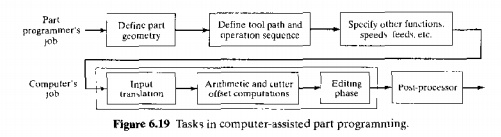
Computer
Tasks in ComputerAssisted Part Programming. The computer's role in
computerassisted part programming consists of the following tasks, performed
more or less in the sequence noted: (1) input translation, (2) arithmetic and
cutter offset computations. (3) editing, and (4) postprocessing, The first
three tasks are carried out under the supervision of the language processing
program. For example, the APT language uses a processor designed to interpret
and process the words, symbols, and numbers written in APT. Other languages
require their own processors. The fourth task, post-processing, re
quires a separate
computer program "I he sequence and relationship of the tasks of the part
programmer and the computer are portrayed in Figure 6.19.
The part
programmer enters the program using APT or some other highlevel part
programming language. The input translation
module converts the coded instructions contained in the program into
computerusable form. preparatory to further processing. In APT, input
translation accomplishes the following tasks: (1) syntax check of the input woe
to identify errors in format, punctuation. spelling, and statement sequence; 12) assigning a sequence number 10
each APT statement in the program; (3) converting geometry elements into a
suitable form for computer processing; and (4) generating an intermediate file
called PROFTL that is utilized in subsequent
arithmetic calculations.
The arithmetic module consists of a set of
subroutines to perform the mathematical computations required to define the
part surface and generate the tool path. including compensation for cutter
offset. The individual subroutines are called by the various statements used in the part programming language, The
arithmetic computations are performed on the PROFIL file. The arithmetic module
frees the programmer from the timecunsuming and errorprone geometry and
trigonometry calculations to concentrate on issues related to workpart
processing. The output of this module is a file called CLFILE, which stands for
"cutter location file." As its name suggests. this file consists
mainly of tool path data.
In editing. the CLFILE is edited. and a new
file is generated called CLDATA. When printed, CLDATA provides readable data on
cutter locations and machine tool operating commands. The machine 1001commands
can be converted to specific instructions during postprocessing. Some of the
editing of CLFILE involves processing of special functions associated with the
part programming language. For example, in APT. one of the special functions is
a COpy command, which provides for copying a tool path sequence that has been
generated in the preceding computations and translating the sequence to a new
location. Another APT instruction processed in the editing phase is lRACUT.
which stands for "transform cutter locations." This instruction
allows a tool path sequence to be transformed from one coordinate system to
another, based on matrix manipulation. Other editing functions are concerned
with constructing tool paths for machines having rotational axes, such as four
and fiveaxis machining centers. The output of the editing phase is a part
program in a format that can be postprocessed for the given machine tool on
which the job will be accomplished
NC
machine tool systems are different. They have different features and
capabilities. Highlevel part programming languages, such as APT, are generally
not intended for only one machine tool type. They arc designed to be genera]
purpose. Accordingly, the final task of the computer in computerassisted part
programming is postprocessing, in
which the CUller location data and machining commands in the CLDATA file arc
converted into lowlevel code that can be interpreted by the NC controller for a
specific machine tool. The output of postprocessing is a part program
consisting of Gcodes, x, yo, and
zcoordinates. S, F,M. and other
functions in word address format. The postprocessor is separate from
the highlevel part programming language. A unique postprocessor must be written
for each machine tool system.
Related Topics