Chapter: Automation, Production Systems, and Computer Integrated Manufacturing : Numerical Control
Manual Part Programming
Manual Part Programming
In manual
part programming, the programmer prepares the NC code using the lowlevel machine language previously described.
The program is either written by hand on a fonn from which a punched tape or
other storage media is subsequently coded, or it is entered directly into a
computer equipped with NC part programming software, which writes the program
onto the storage media. In any case. the part program is a blockbyblock listing
of the machining instructions for the given job, formatted for the particular
machine tool to be used.
Manual
part programming can be used for both pointtopoint and contouring jobs. It is
most suited for pointtnpoint machining operations such as drilling. It can also
be used for simple contouring jobs, such as milling and turning when only two
axes are in valved. However, for complex threedimensional machining operations,
there is an advantage in using computerassisted part programming
Instructions
in Word Address Format. Instructions in word address torrnat consist of a
series of words, each identified by a prefix label. In our coverage, statement, are
illustrated with dimensions given in millimeters. The values are expressed in
four digits ineluding one decimal place. For example. X020.0 means x = 20,0
rnrn. It should be noted that manv CNC machines use formats that differ from
ours, and so the instruction manual for each particular machine tool must be
consulted to determine its own proper format. Our format is designed to convey
principles and for easy reading.
Tn
preparing the NC part program, the part programmer must initially define the
origin of the coordinate axes and then reference the succeeding motion commands
to this axis system. This is accomplished in the first statement of the part
program. The directions of the X, y, and/or aaxes are predetermined by the machine tool
configuration, but the origin of the coordinate system can be located at any
desired position. The part programmer defines this position relative to some
part feature that can be readily recognized by the machine operator. The
operator is instructed to move the tool to this position at the beginning of
the job. With the tool in position, the G92 code is used by the programmer to
define the origin as follows:
G92
XOY050,0 ZOIO.0
where the
x,)', and z values specify the
coordinates of the tool location in the coordinate system; in effect, this
defines the location of the origin. In some CNC lathes and turning centers, the
code G50 is used instead of G92. Our .r, y, and z values are specified in millimeters, and this would have to be
explicitly stated. Thus, a morecomplete instruction block would be the
following:
G21 G92 XO
YOSO,O ZOlO.O
where the ti21 code indicates that
the subsequent coordinate values
are in millimeters.
Motions
are programmed by the codes 000, GOL 002, and G03. GOOis used for a
pointtopoint rapid traverse movement of the tool to the coordinates specified
in the command; for example,0
000 X050.0Y086.5 ZI00.0
specifies
a rapid traverse motion from the current location to the location defined b)
the coordinates r = 50.0 mrn, y = 86.5 mill, and z = 100.0 mill.
This command would be appropriate for NC drilling machines in which a rapid
move is desired to the next hole location. with no specification on the tool
path. The velocity with which the move is achieved in rapid traverse mode is
set by parameters in the MCV and is not specified numerically in the
instruction block. The GOO code is not intended for contouring operations,
Linear
interpolation is accomplished by the 001 code. This is used when it is desired
for the tool to execute a contour cutting operation along a straight line path.
For example, the command
GOI
094 X050.0 Y086.5 Z100.0 F40 5800
specifies
that the 1001 is to move in a straight line from its current position to the
location definedbyx = 50.0mm,y 0= 86.5 mm.and z '" irnn mm.et a feed rate of 40 mrn/rnin and spindle speed of 800 rev Imin.
The G02
and G03 codes are used for circular interpolation, clockwise and
counterclockwise, respectively. As indicated in Table 6.1, circular
interpolation on a milling machine is limited to one of three planes, xy, xz, or yz. The distinction between
clockwise and counterclockwise is established by viewing the plane from the front view, Selection of the desired plane
is accomplished by entering one of the codes,G17, G IS, or 019, respectively. Thus, the
instruction
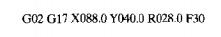
moves the
tool along a clockwise circular trajectory in the x y plane to the final coordinates
defined by x = 88 nun and y = 40 mm at
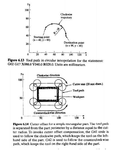
a feed rate of 30 mm/min. The radius of the circular arc is 28 mm. The path
taken by the cutter from an assumed starting point (x = 40, Y = 60) is illustrated in FIgure 6.13
In a
point-to-point motion statement (GOO), it is usually desirable to position the
tool so that its center is located at the specified coordinates. This is
appropriate for operations such as drilling, in which a hole is to be
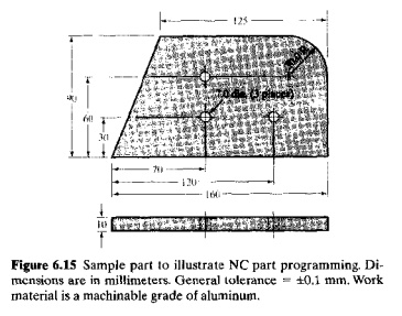
positioned at the coordinates indicated in the statement. But in contouring
motions, it is almo~t always desirable that the path followed by the center of
the tool be separated from the actual surface of the part by a distance equal
to the cutter radius. This is shown in Figure 6.14 for profile milling the
outside edges of a rectangular part in two dimensions. For a threedimensional
surface, the shape of the end of the cutter would also have to be considered in
the offset computation. This tool path compensation is called the cutter offset, and the calculation of
the correct coordinates of the endpoints of each move can be time consuming and
tedious for the part programmer. Modern CNe machine tool controllers perform
these cutter offset calculations automatically when the programmer uses the
G40, G41, and G42 codes. The 040 code is used to cancel the cutter offset
compensation.The 041 and G42 codes invoke the cutter
offset compensation of the tool path on the left or righthand side of the part,
respectively. The left and righthand sides are defined according to the tool
path direction. To illustrate, in the rectangular part
in Figure
6.14, a clockwise tool path around the part would always position the tool on
the lefthand side of the edge being cut, so a 041 code would be used to compute
the cutter offset compensation. By
contrast, a counterclockwise tool path would keep the tool onthe righthand side
of the part, so G42 would be used. Accordingly, the instruction for profile
milling the bottom edge of the part, assuming that the cutter begins along the
bottom left comer, would read:
G42 Got X
I00.0 Y04O,O D05
where D05
refers to the cutter radius value stored in MCV memory. Certain registers are
reserved in the control unit for these cutter offset values. The Dcode
references the value contained in the identified register. D05 indicates that
the radius offset distance is stored in the number 5 offset register in the
controller. This data can be entered into the controller in either of two ways:
(1) as manual input or (2) as an instruction in the part program. Manual input
is more flexible because the tooling used to machine the part may change from
one setup to the next. At the time the job is run, the operator knows which
tool will be used. and the data can be loaded into the proper register as one
of the steps in the getup. When the offset data is entered as a part program
instruction, the statement has the form:
GIO P05
RlO.O
where G
10 is a preparatory w ord indicating that cutter offset data will be entered;
P05 indicates that the data will be entered into offset register number 05; and
RIO,() is the radius value,herelO.Omm.
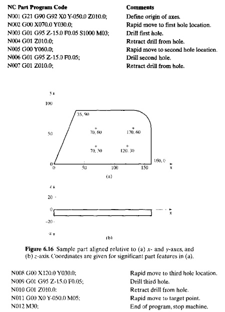
SomePart
Programming Examples. To demonstrate manual part programming, we
present two examples using the sample part shown in Figure 6.1S.The first
example is a pointtopoint program to drill the three holes in the part. The
second example is a twoaxis contouring program to accomplish profile milling
around the periphery of the part.
This
example presents the NC part program in word address format for drilling the
three holes in the sample part shown in Figure 6.15. We assume that the outside
edges of the starting workpart have been rough cut (by jig sawing) and are s1Jgbtly
oversized for subsequent profile milling. The three holes to be drilled in
thi:; example will be used to locate and fixture the part for profile milling
in the following example. For the present drilling sequence, the part is
gripped in place so that its top surface is 40 rnrn above the surface of the
machine tool table to provide ample clearance beneath the part for hole
drilling. We will define the X. y.and zaxes as shown in Figure 6.16.A
7.omm diameter drill,oorresponding to the specified hole size, has been chucked
in the eNC drill press. The drill will be operated at a feed of 0.05 mm/rev and
a spindle speed of 1000 rev/min (corresponding to a surface speed of about 0.37
rn/sec, which is slow for the aluminum work material). At the beginning of the
job, the drill point will be positioned at a target point located atx = O,y = So,and z = +10
(axis units are millimeters). The program begins with the tool positioned at
this target point.
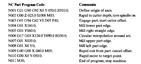
EXAMPLE 6.2 Two Axis Milling
The three holes drilled in the previous
example can be used for locating and holding the workpart to completely mill
the outside edges without refixturing The axis coordinates are shown in Figure
6,16 (same coordinates as in the pre vious drilling sequence). The part is
Iixtured so that its top surface is 40 mm above the surface of the machine tool
table. Thus, the ongin of the axis system will be 40 mm above the table
surface. A 20mm diameter end mill with four teeth will be used. The cutter has
a side tooth engagement length of 40 mm. Throughout the machining sequence, the
bottom tip of the cutler will be positioned 25 mm below the part top surface.
which corresponds to Z = 25 mrn. Since the part is 10 mm thick, this zposuion
will allow the side cutting edges of the milling cutter to cut the full
thickness of the part during profile milling. The cutter will be operated at a
spindle speed = 1000 rev/min (which corresponds to a surface speed of about 1.0
m/sec) and a feed rate = 50 mm/min (which cor responds 10 0.20 rnm/tooth). The
tool path to be followed by the culler is shown
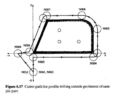
in Figure
6.17, with numbering thai corresponds to the sequence number in the program.
Cutter diameter data has been manually entered into offset register 05. At the
beginning of the job, the cutter will be positioned so that its center tip is
at a target point located at x = O. Y = 50, and t; = +10. The
program begins with the tool positioned at this location.
Related Topics