Chapter: Automation, Production Systems, and Computer Integrated Manufacturing : Numerical Control
Numerical Control Coding System
NC PART PROGRAMMING
NC part
programming consists of planning and documenting the sequence of processing
steps 10 be performed on an NC machine. The part programmer must have a
knowledge of machining (or other processing technology for which the NC machine
is designed) as well as geometry and trigonometry. The documentation portion of
par! programming involves the input medium used to transmit the program of
instructions to the NC machine control unit (MCU). The traditional input medium
dating back to the first NC machines in the 1950s is linch wide punched rape,
More recently the use of magnetic tape and floppy disks have been growing in
popularity as storage technologies for NC Th ••,
advantage. of these input media is their much higher data density.
Part programming can he accomplished using a variety of procedures ranging from highly manual to highly automated methods. The methods are: (1) manual part programming, (2) computerassisted part programming, (3) part programming using CAD/CAM. and (4) manual data input. These part programming techniques are described in this section. Let us begin our presentation by explaining the NC coding system used to convoy the part program to the machine tool
NC Coding System
The
program of instructions is communicated to the machine tool using a coding
system based on binary numbers. This NC coding system is the low-level machine language
that can be understood by the MCU. when higher
level languages are used. such as A[Yf (Section 6.5.4), the statements in the
program are converted to this basic code. In the present section, we discuss
how instructions are written in this NC code to control the relative positions
of the tool and workpiece and to accomplish
the other functions of the machine tool.

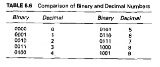
Conversion
of the 10 digits in the decimal number system into binary numbers is shown in
Table 6,6. Four binary digits are required to represent the ten singledigit
numbers in decimal. Of course, the numerical data required in NC includes large
decimal values; for example, the coordinate position .r = 1250 rnrn. To encode the decimal
value 1250 in the binary number system requires a total of 11 digits:
10011100010. Another problem with the binary number system is the coding of
decimal fractions, for example, feed = 0.085
mm/rev.
To deal
with these problems in NC, a combination of the binary and decimal number
systems has been adopted, called the binarycoded
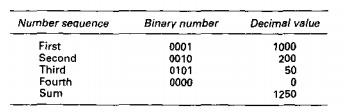
decimal (BCD) system. In this coding scheme, each of the ten digits (09) in
the decimal system is coded as a fourdigit binary number, and these binary
numbers are added in sequence as in the decimal number system. For example, the
decimal value 1250 would be coded in BCD as follows:
EIA and
ISO Coding Standards. In addition to numerical values, the NC coding system
must also provide for alphabetical characters and other symbols. Eight binary
dig. its are used to represent all of the characters required for NC part
programming. There are two standard coding systems currently used in NC: (1)
the Electronics Industry Association (EIA) and (2) the International Standards
Organization (ISO). The Electronics Industry Association system is known as EIA
RS244R The ISO code was originally developed as the American Standard Code for
Information Interchange (ASCII) and has been adopted by ISO as its NC standard.
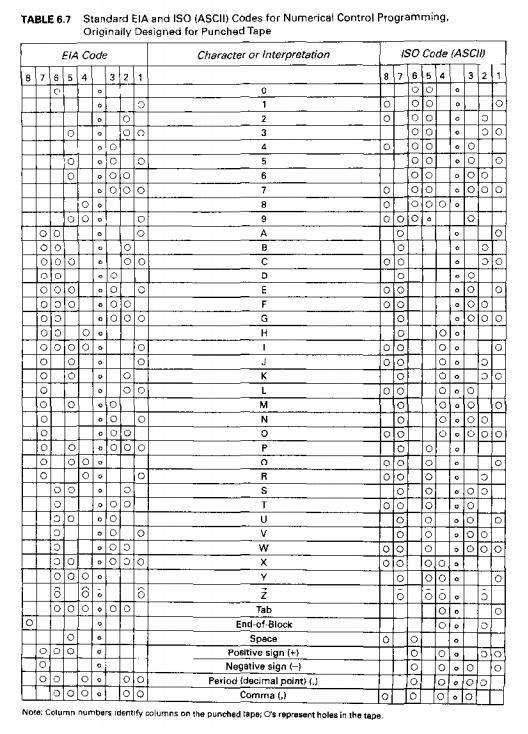
The complete listings of EIA and ISO (ASCII) codes for NC are shown in Table
6.7. Many NC controllers are capable of reading either code,
Both EIA
and ISO coding schemes were developed when punched tape was the predominant
medium fur storing NC part programs. Although punched tape has been largely
superseded by more modern media. it is still widely used in industry. if only
for backup storage. To ensure the correctness of the punched tape. the eight
binary digits in the EIA and ISO codes include a paru» check. Here's how the parity check work, explained here

ber of
holes across the width of the tape. Whenever the particular number or symbol
being punched requires an even number of holes. an extra hole is punched in
column 5, hence making the lotal an odd number. For example, the decimal
numberS is coded by means of holes in columns 1 and 3. Since this is an even
number of holes, a parity hole would be: added. The decimal 7 requires an odd
number of holes (in columns 1, 2, and 3),so no parity hole is needed. The
parity check helps 10 ensure that the tape punch mechanism has perforated a
complete hole in all required positions. If the tape reader counts an even
number of holes. then a signal is issued that a parity error has occurred.
The
difference between the EIA and ISO systems is that the parity check in the ISO
code i~ an even number of holes, called an even
parity. The EIA system uses an odd
parity.Aho. whereas the parity hole is in the fifthdigit position in the
'EIA coding system, it is in the
eighth position in the ISO system. These differences can be seen in Table 6.7
How tnstructions Are Formed. A binary digit is called a bit. In punched tape, the values 0 or 1 are represented by the
absence or presence of a hole in a certain row and column position (rows run
across the tapecolumns run lengthwise along the tape). Out of one row of bits a
character is formed. A character is a
combination of bits representing a numericaldigit (09), an alphabetical letter
(AZ),or a symbol (Table 6.7). Out ofa sequence of characters, a word is formed.
A wont specifies a detail about the
operation, such as .rposition, ypositlon, feed rate, or spindle speed. Out of a
collection of words, a block is formed. A block
is one complete NC instruction. It specifies the destination for the move, the
speed and feed of the cutting operation. and other commands that determine
explicitlywhat the machine tool will do. For example, an instruction block for
a twoaxis NC milling machine would likely include the x and vcoordinates to which the machine table should be moved, the
type of motion to be performed (linear or circular interpolation), the rota
tional
speed of the milling cutler, and the feed rate at which the milling operation
should be performed. Imtn.lction blocks arc separated by an endofblock (LOB)
symbol (a hole
in column
8 in the EIA standard or holes in columns 2 and 4 in the ISO standard. as in
Table 6.7).
The
essential information in a part program is conveyed to the MCU by means of
words that specify coordinates, feeds and speeds, tooling, and other commands
necessary to operate the machine tool. Given the variety of machine tool types
and the many different companies that build NC machine tools and MCUs, it is no
surprise that several different formats have been developed over the years to
specify words within an instruction block. These are often referred to as tape
formats, because they were developed for punched tapes, More generally, they are
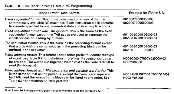
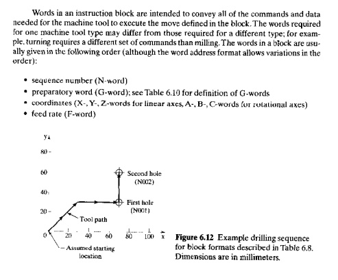
known as block formats. At least five
block formats have been developed [8]; these are briefly described in Table
6.8, with two lines of code for the drilling sequence shown in Figure 6.12
The word
address format with TAB separation and variable word order has been
standardized by EIA as RS·274. It is the block format used on all modern
controllers and is the format we will discuss hcre.It is usually referred to
simply as the word address format even though it has been enhanced by tab
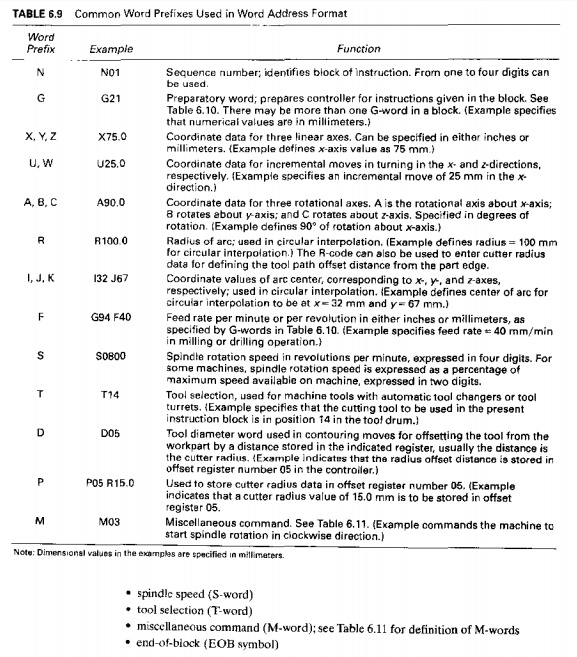
separation and variable word order. Com. man letter prefixes used in the word
address format are defined in Table 6.9.
Words in
an instruction block are intended to convey all of the commands and data needed
for the machine tool to execute the move defined in the block. The words
required for one machine tool type may differ from those required for a
different type; for example. turning requires a different set of commands than
milling. The words in a block are usually given in the following order
(although the word address format allows variations in the order):
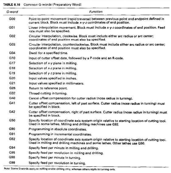
G-words and Mwords require some elaboration. Gwords are
called preparatory words. They
consist of two numerical digits (following the "G" prefix in the word
address for mat) that prepare the MeU for the
instructions and data contained in the block. For example, G02 prepares the
controller for clockwise circular interpolation, so that the subsequent data in
the block can be properly interpreted for this type of move. In some cases,
more than one Gword is needed to prepare the MeU for the move. Most of the common Gwords are presented in Thble
6.10.While Gwords have been standardized in the machine tool industrv, there
arc sometimes deviations for particular machines. For instance, there are several
differences between milling and turning type machines; these are identified in
Table 6.10.
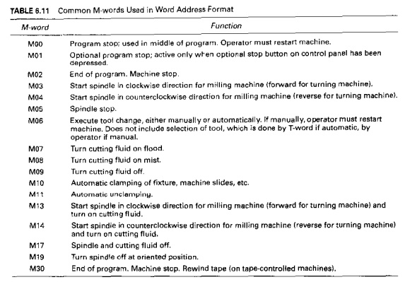
M-words
are used to specify miscellaneous or auxiliary functions that an: available on
the machine tool. Examples include starting the spindle rotation, stopping the
spindle for a tool change, and turning the cutting fluid on or off. Of course,
the particular machine tool must possess the function that is being called.
Many of the common M-words are explained in Table 6.11. Miscellaneous commands
are normally placed at the end of the block.
Related Topics