Chapter: Automation, Production Systems, and Computer Integrated Manufacturing : Numerical Control
Part Programming with APT
Part Programming
with APT
In this
section, we present some of the basic principles and vocabulary of the APT
language. APT is an
acronym that stands for Automatically Programmed Tooling. It is a
three dimensional NC part programming system that was developed in the late
19508 and early 60s (Historical Note 6.3). Today it remains an important and
widely used language in the United States and around the world. APT is also
important because many of the concepts incorporated into it termed the basis
for other subsequently developed languages. APT was originally intended as a
contouring language. but modern versions can be used for both point to point and
contouring operations in up to five axes. Our discussion will be limited to the
three linear axes, x, y, and z.APT can be used for a variety of
machining operations.
Our
coverage will concentrate on drilling (point to point) and milling (contouring)
operations. There are more than 500 words in the APT vocabulary. Only a small
(but important) fraction of the total lexicon will be covered here. The
Appendix to this chapter lists some of these important APT words.

The
reader must remember that the work described in this historical note was
started in the 1950s,a lime when digital computer technology was in its
infancy, and so were the associated computer programming languages and methods.
The APT project was a pioneering effort, not only io the development of NC
technology, but also in computer programming concepts, computer graphics, and
computeraided design (CAD).
It was
recognized early in the NC development research at MIT that part programming
would be a timeconsuming task in the application of the new technology, and
that there were opportunities to reduce the programming time by delegating
portions of the task to a genetaI_purpo.e computer. In June 1951, even before
the first experimemal NC machine was operating, a study was undertaken to
explore how the digital computer might be used as a programming aid. The result
of this study was a recommendation that a set of computer programs be developed
to perform the mathematical computations that otherwise would have to be
accomplished by the part programmer. In hindsight, the drawback of this
approach was that, while it automated certain steps in the part programming task,
the basic manual programming procedure was preserved
The
significant breakthrough in computerassisted part programming was the
development of the automatically programmed 1001 system (APT) during the years
19561959. It was the brainchild of mathematician Douglas Ross, who worked in
the MIT Servomechanisms Lab at the time. Ross envisioned a part programming
system in which (1) the user would prepare instructions for operating the
machine tool using Englishlike words, (2) the digital computer would translate
these instructions into a language that the computer could understand and
process. (3) the computer would carry out the arithmetic and geometric
calculations needed to execute the instructions. and (4) the computer would
further process (postprocess) the instructiOn! 'u that they could be
interpreted by the machine tool controller. He further recognized that the
programming system should be expandable for applications beyond those
considered in the immediate research (milling applications).
Around
this time, the Aircraft Industries Association (AlA, renamed the Aerospace
Industries Assoclation in 1959) was attempting to deal with NC part programming
issues through its Subcommittee on Numerical Control (SNC). Ross was invited 10
attend a meeting of the SNC in January 1957 to present his views on
computerassisted part programming. The result 01 this meeting was that Rosa's
work at MIT was established as a focal poinl for NC programming within thc AlA,
A project was initiated in Apri11957to develop a twodimensionill version of
APT, with nine alrcrafr companies plus IBM Corporation participating in the
joint effort ami MIT as project coordinator. The 2DAPT system was ready for
field evaluation at plant, of participating companies in April 1958.Testing,
debugging, am] refining the programming system took approximately three
years.during which time the AlA assumed responsibllity for further APT
development. In 1961, the Illinois Institute of Technology Rcsearch lnslituto;
(lITRl) was selected by the AlA to become the agency responsible
for longrange maintenance and upgrading of Al'T'In 1962,IITRI announced
completion of APTIII. a commercial version 01APT for threedimensional part
programming. In 1974,APT was accepted as the U.S.standard for programming NC
metal cutting machine tools. In 1978,it was accepted by the ISO as the
international standard.
One of
the initial problems with APT when it was released in the early 1960swas that a
very large computer was required 10execute it, thereby limiting the number of
companies that could use it Several part programming languages based directly
on APT were developed to address this problem. Two of the more important
APTbased languages were ADAPT and EXAPT. ADAPT (ADaptation of APT) was
developed by IBM under Air Force contract to include many of the features of
APT bUI required a much smaller computer. ADAPT can be used for both
pointtopoint and contouring jobs. EXAPT (EXtended subset of APT) was anolher NC
part programming language based on APT. EXAPT was developed in Germany around
1964in three versions',(1) EXAPT I was designed for pointtopoint applications,
such as drilling and straight milling; (2) EXAPT 11was developed for turning
operations; and
(3) EXAPT
III was capable of limited contouring for milling.
APT is
not only a language; it is also the computer program that processes the APT
statements to calculate the corresponding cutter positions and generate the
machine tool control commands. To program in APT. the part geometry must first
be defined. Then the tool is directed to various point locations and along
surfaces of the workpart to accomplish the required machining operations. The
viewpoint of the programmer is that the workpiece remains stationary and the
tool is instructed to move relative to the part. To complete the program,
speeds and feeds must be specified, tools must be called, tolerances must be
given for circular interpolation, and so forth. Thus, there are four basic
types of statements in the APT language:
Geometry
statements, also called
definition statements, are used to define the geometry elements that
comprise the part.
Motion commands
are used to specify the tool path.
Post-processor
statements control the machine tool operation, for example, to
specify speeds and feeds, set
tolerance values for circular interpolation, and actuate other capabilities of
the machine tool.
Auxiliary statements, a group
of miscellaneous statements used to name the part program, insert comments in
the program and accomplish similar functions.
These
statements arc constructed of APT vocabulary words, symbols. and numbers, all
arranged using appropriate punctuation. APT vocabulary words consist of six or
fewer characters. 1 he characters are almost always letters of the alphabet.
Only a very few APT vocabulary words contain numerical digitsso few in fact
that we will not encounter any of them in our treatment of APT in this chapter.
Most APT statements include a slash (I) as part of the punctuation. APT
vocabulary words that immediately precede the slash arc called major words. whereas those that follow
the slash are called minor words.
Geometry Statements. The
geometry of the part must be defined to identify the surfaces and features that are to be machined. Accordingly, the
points, lines, and surfaces must be defined in the program prior to specifying
the motion statements. The general form of an APT geometry statement is the
following:
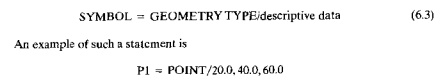
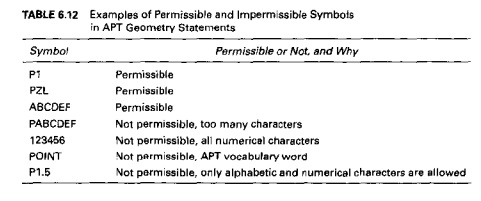
An APT
geometry statement consists of three sections. The first is the symbol used to
identify the geometry element. A symbol can be any combination of six or fewer
al phabetical and numerical characters, at least one of which must be alphabetical.
Also, the symbol cannot be an APT vocabulary word. Some examples are presented
in Table 6.12 to illustrate what is permissible as a symbol and what is not.
The second section of the APT geometry statement is an APT major word that
identifies the type of geometry element. Examples are POINT, LINE, CIRCLE, and
PLANE. The third section of the APT geometry statement provides the descriptive
data that define the element precisely, completely, and uniquely. These data
may include numerical values to specify dimensional and position data,
previously defined geometry dements, and APT minor words.
Punctuation
in an APT geometry statement is indicated in Eq. (6.3). The definition
statement is written as an equation, the symbol being equated to the geometry
element type, followed by a slash with descriptive data to the right of the
slash. Commas are used
to
separate the words and numerical values
in the descriptive data.
There arc
a variety of ways lu spectry the various geometry elements. The Appendix to
this chapter presents a sampling of statements for defining the geometry
elements we
will be
using in our treatment of APT: poiuts.Iines, planes, and circles. The reader
may benefit from a few examples:
Points.
PI
"' POINI!2IJ.U,40.U,60.0
where the
descriptive data following the slash indicate the X·, yo, and zcoordinates.
The specification can be done in either inches or millimeters (metric). We use
metric values in our examples. As an alternative, a point can be defined as the
intersection of two mtersecrmg lines, as in the following
P2 =
POINTfINTOF, Lt. L2
where the
APT word INTOF in the descriptive data stands for "intersection of."
Other methods of defining points are given in the Appendix under POINT
Lines.
A line
defined in APT is considered to be of infinite lengtb in hoth directions. Also, APT
treats a line as a vertical plane that is perpendicular to the .rj' plane. The
easiCStway to specify a line is by two points through which it passes:
L3 = LINE/P3. P4
In some
situations, the part programmer may find it more convenient to define a new
line as being parallel to another line that has been previously defined; for
example,
L4 =
LlNEIP5, PARLEL, L3
where
PARLEL is APT's way of spelling "parallel."The statement indicate,
line l4 passes through point PS and is parallel to line L3.
Planes.
A plaue
can be defined by specifying three points through which the plane passevasin
the following'
PLl =
PLANE/Pl.P2,P3
Of
course. the three points must he noncollinear. A plane can also be defined as
being parallel to another plane that has been previously defined; for instance,
PL2 =
PLANE!P2, PARLEL, PLl
which
states that plane PL2 passes tbrough point P2 and is parallel to plane PLI. In
APT, a plane extends indefinitely.
Circles. In APT, a circle is considered to be a cylindrical surface that
is pcrpendic
ular to
the xj plane and extends to infinity in the zdircction. The easiest way to
define a circle i~ by its
center and radius. as in the following
Cl = CIRCLE/CENTER,Pl,RADIUS,25.0
By
convention. the circle is located in the .e.y plane. An alternative way of
defining a circle i~to
specify thur it passes through three points; for example,
C2 = CIRCLE/P4, P5, P6
where the
three points must not he collinear There are m;'lny other ways to define a ciretc, several of which are listed in the
Appendix under CIRCLE
Certain ground rules
must he obeyed when formulating APT geometry statements.
Following are four important APT rules:
t. Coordinate data must be specified in the order x, then y, then z, because the statement
PI = POINT/20.5,40,O,60.0
is
interpreted to mean x =
20.5 mm,y =
40.0 mm.
and e = 60.0 mm
Any
symbols used as descriptive data must have been previously defined; for example.In
the statement
P2 = POINT/JNTOF,Ll,L2
the two
lines Ll and L2 must have been previously defined. In setting up the list of
geometry statements, the APT programmer must be sure to define symbols before
using them in subsequent statements.
A symbol
can be used to define only one geometry element. The same symbol cannot be used
to define two different elements. For example. the following statements would
be incorrect if they were included in the same program:
Pl = POINTI20,40,60
PI = POINT 130,50,70
Only one
symbol can be used to define any given element. For example, the following two
statements in the same r"rt program would be incorrect;
PI =
POINTI20,40,60
P2 =
POINT/20,40,60
EXAMPLE 6.3 Part Geometry Using APT
Let us
construct the geometry of our sample part in Figure 6.15. The geometry dements
of the part to be defined in APT are labeled in Figure 6.18. Reference is also
made to Figure 6.16, which shows the coordinate values of the points used to
dimension the part. Only the geometry statements are given in the APT sequence
that follows:
PI = POINT 10,0,0
P2 = POiNT/160.0,O,O
P3 = PUINT /160.0.60.0,0
P4 =
POINT/35.0.90.0.0
P5 = POINT/70.0.30.0.0
P6 = POINT/120.0.30.0,0
P7 =
POINT /70.0.60.0,0
P8 =
POINT /130.0.60.0,0
L1 = LINE/Pl,P2
L2 = LINE/P2, P3
Cl =
CIRCLE/CENTER, P8, RADIUS. 30.0
L3 = L1NE/1'4, PARLEL, L1
L4 = LINE/P4, PI
Motion Commands. All APT
motion statements follow a common fonnat,just as geometry statements have their own format. The format of an APT
motion command is'
MOTION COMMAND/descriptive data (6.4)
An
example of an APT motion statement is
GOTOIPI
I'he
statement consists of two sections separated by a slash. The first section is
the basic command that indicates what move the tool should make. The
descriptive data following the slash tell the tool where to go. In the above example, the tool is
directed to go to (GOTO) point PI, which has been defined in a previous
geometry statement.
At the
beginning of the sequence of motion statements, the tool must be given II starting point. This is likely
to be the target point. the location where the operator has positioned the tool
at the start of the job.The part programmer keys into this starting position
with the following statement:
fROM/PTARG {651
where
FROM is anAPT vocabulary word indicating that this is the initial point from
which all others will be referenced; and PTARO is the symbol assigned to the
starting point. Another way to make this statement is the following'
FROMj20.0. 20.0,0
where the
descriptive data in this case arc the X, y, and zcoordinates of the starting point. The FROM statement
occurs only at the start of the motion sequence.
In our
discussion of APT motion statements, it is appropriate to distinguish between pointtopoint motions and contouring
motions. For potnrtopoiru motions,
there are onl two commands: GOTQ and GODLTA.The GOTO statement instructs the
tool to go to a particular point location specified in the descriptive data.
TWo examples are:
GOTOIP2 (6.6,)
001'0/25.0,40,0,0 (6.6b)
In the
first command, P2 is the destination or the too] point. In the second command,
the 1001 has been instructed to go to the location whose coordinates are x =
25.0, Y = 40.0, and z = O.
The
GODLTA command specifies an incremental move for the tool.To illustrate, the
following statement instructs the tool to move from its present position by a
distance of 50.0 mm in the xdirection, 120.0 mm in the ydirection, and 40 rum
in the zdirection
GODLTA!50.0, 120.0, 40.0
The GODLY
A statement is useful in drilling and related machining operations. The tool
can be directed to go to a given hole location; then the GODLTA command can be
used to drill the hole, as in the following sequence:
GOTO/P2
GODLTA/[), 0, 50.0
GODLTAjO,0,50.0
Contouring
motion commands are more complicated than PTP commands are because the tool's
position must be continuously controlled throughout the move. To exercise this
control. the tool is directed along two intersecting surfaces until it reaches
a third surface, as shown in Figure 6.20. These three surfaces have specific
names in APT; they are:
Drive surface. This is the surface that
guides the side of the cutler. It is pictured as II plane in our figure.
Part surface. This is the surface, again
pictured as a plane, on which the bottom or nose of the tool is guided.
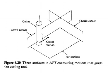
Check;
surface. This is the surface that stops the forward motion of the tool in the
execution of the current command. One might say that this surface
"checks" the advance of the tool.
It should
be noted here that the "part surface" mayor may not be an actual
surface of the part The part programmer may elect to use an actual part surface
or some other previously defined surtace for the purpose of maintaining
continuous path control of the tool. The same qualification goes for the drive
surface and check surface.
There are
several ways in which the check surface can be used. Ifus is determined by
using any of four APT modifier words in the descriptive data of the motion
statemen!. The four modifier words arc TO, ON, PAST. and TANTO. As depicted in
Figure 0.21, the word TO positions the leading edge of the tool in contact with
the check surface; ON positions the center of the tool on the check surface;
and PAST puts the tool beyond the check surface. so that its trailing edge is
in contact with the check surface. The fourth modifier word TANTO is used when
the drive surface is tangent to a circular check surface, as in Figure 6.22.
TANTO moves the cutting tool to the point of tangency with the circular surface
An APT
contouring motion command causes the cutter to proceed along a trajectory
defined by the drive surface and part surface; when the tool reaches the check
surface it stops according to one of the modifier words TO, ON, PAST, or TANTO.
In writing a
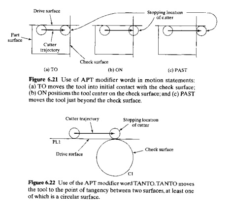
Figure 6.23
Use of the APT motion words. The tool has moved from a previous position
10 its present position. The
direction of the next move is
determined by one of the APT motion
words GOLFT. GORGT, GOFWD, GOBACK, GDUP,
or GODOWN.
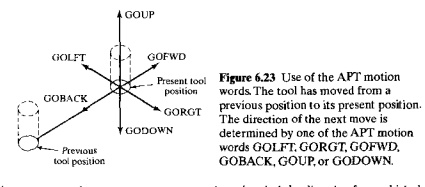
motion
statement, the part programmer must keep in mind the direction from which the
tool is coming in the preceding motion command. The programmer must pretend to
be riding on top of the tool, as if driving a car. After the tool reaches the
check surface in the preceding move, does the next move involve a right tum or
left tum or what? The answer to this question is determined by one of the
following six motion words, whose interpretations are illustrated in Figure
6.23:
GOLIT commands
the tool to make a left tum
relative to tbe last move.
GORGT commands
the tool to make a right tum relative
to the last move.
GOFWD commands
the tool to move forward relative
to the last move.
GOBACK commands
the tool to reverse
direction relative to the last move.
GOUP commands
the tool to move upward
relative to the last move
GODOWN commands
the tool to move down relative to
the last move.
In many
cases, the next move will be in a direction that is a combination of two pure
directions. Forexample, the direction might be somewhere between go forward and
go right. In these cases, the proper motion command would designate the largest
direction component among the choices available.
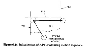
To begin
the sequence of motion commands, the FROM statement,Eq. (6.5) is used in the
same manner as for pointtopotnt moves. The statement following the FROM command
defines the initial drive surface. part surface, and check surface. With
reference to Figure 6.24. the sequence takes the following form:
FROMiPTARO
oo/ro,
flLl, TO. PL2, TO PL3 (6.7)
The
symbol PTAR.G represents the target point w~ere the ?perator has. set up the
tool. The GO command Instructs the tool to move to the mtersecnon of the drive
surface (PL1), the part surface (PL2), and the check surface (PL3). Because the
modifier word TO has been used for each of the three surfaces, the
circumference of the cutter is tangent to PLI and PL3. and the bottom of the cutler
is on PL2. The three surfaces included in the GO statement must be specified in
the order: (I) drive surface, (2) part surface, and (3)checksurlacc
Note that
GO/TO is not the same as the 001'0 command. Eq. (6.6). 001'0 is used only for
JYrp motions. The GO/ command is used to initialize a sequence of contouring
motions and may take alternative forms such as GO/ON, GorrO, or GOIPAST.
After
initia'ization, the tool is directed along its path by one of the six motion
command words. It is [Jot necessary to redefine the part surface in every
motion command after it has been initially defined as long as it remains the
same in subsequent commands. In the preceding motion command, Pq. (6.7), the
cutter has been directed from P"IARG to lhe interscction of surfaces PLI,
PL2, and PL3. Suppose it is now desired to move the tool along planc PL3 in
Figure 6.24, with PL2 lCllw.i"ing a~ the pan surface. The following
command would accomplish this motion:
GORGT!PL3, PAST,PL4
Note that
PL2 is not mentioned in this new command. PD, which was the check surface in
the preceding command, Eq. (6.7), is the drive surface in the new command. And
the new check surface is PL4. Although the part surface may remain the same
throughout the motion sequence. the drive surface and check surface must be
redefined in each new contouring motion command.
There arc
many parts whose features can all be defined in two axes, x and y. Although such
parts certainly possess a third dimension, there are no features to be machined
in this direction. Our sample part is a case in point. In the engineering
drawing, Figure 6.15, the sides of the part appear as lines, although they lire
threedimensional surfaetls on the physical part. In cases like this, it is more
convenient for the programmer to define the pan profile in terms of lines and
circles rather than planes and cylinders. Fortunately, the APT language system
allows this because in APT, lines me treated as planes and circles are treat.
ed as cylinders, which are both perpendicular to the ry plane. Hence, the planes around the part outline in Figure 6.15
can be replaced by lines (call them Ll, L2, L3, and L4), and the APT commands
in Bqs (6.7) and (6.8) can be replaced by the following:
fROM/PTARG
oo/ro. Ll,
TO, PL2, TO L3
GORGT/L3, PAST,L4
Substitution
of lines and circles for planes and cylinders in APT is allowed onlv when the
sides of the pall are perpendicular to the xy
plane. Note that plane PL2 has not been converted to a line. As the "part
surface" in the motion statement, it must maintain its status as a plane
parallel to the .r and yaxes,
EXAMPLE 6.4 APT Contouring Molion Commands
Let
U~write the AM' motion commands to profile mill the outside edges of our sample
workpart. The geometry clements are labeled in Figure 6,18, and the too! path
is shown in Figure 6.17. The tool begins its motion sequence from a target
point PTARG located at x = 0, y = 50 mm and l = 10 rnm. We also assume that
"part surface" PL2 has been defined as a plane parallel to the xy
plane and located 25 mm below the top surface of the part (Figure 6.16), The
reason for defining it this way is to ensure that the cutter will machine the
entire thickness of the part.
FROMlPTARG
GO/TO. L1, TO, PL2. ON,L4
GORGT/Lt, PAST, L2
GOLFTfL2, TANTO,
Cl
GOFWDtCL PAST. L3
GOFWD/L3, PAST, L4
GOLFf/L4, PAST, L1
GOTO/PO
Postprocessor and
Auxiliary Statements. A complete APT
part program must
include
functions not accomplished by geometry statements and motion commands. These
additional functions are implemented by postprocessor statements and auxiliary
statements.
Postprocessor
s[{]/emenls control the operation of the machine tool and playa supporting role
in generating the tool path. Such statements are used to define cutter size,
specify
speeds and feeds, turn coolant flow on and off,
and control other features of
the par
ticular machine
tool on which the machining job will be performed. The general form of a
postprocessor statement
is the following:
POSTPROCESSOR COMMAND/descriptive data
(6.9)
where the
POSTPROCESSOR COMMAND i~an APT major word indicating the type of function or
action to be accomplished, and the descriptive data consists of APT minor words
and numerical values. In some commands. the descriptive data is omitted. Some
exarnples of postprocessor statements that appear in the Appendix at the end of
the chapter arc the following:
llNITSiMM
indicates that the specified units used in the program an: INCHES
or Mlv1.
INTOL/O.02 specifies
inward tolerance for circular
interpolation.
OUTTOLjO.02 specifies
outward tolerance for circular
interpolation.
eUTTERj20.0 defines cutter diameter for
tool path offset calculations; the length and other dimensions of the tool can
also be specified, if necessary, for threedimension, at machining.
SPINDLjlOOO, CLW specifies spindle
rotation speed in revolutions per minute. Either CLW (clockwise) or eeLW
(counterclockwise) can be specified
SPINDLIOFF stops
spindle rotation.
FED RAT /
40, IPM specifies feed rate in millimeters per minute or inches per minute.
Minor words IPM or IPR are used to indicate whether the feed rate is units per
minute or units per revolution of the cutter, where the units are specified as
inches or millimeters in a preceding UNITS statement.
RAPID engages
rapid traverse (high feed rate) ror nexc movers}.
COOLNT/FLOOD turns CUlling fluid
on
LOADTL/Ol
used with automatic toolchangers to identify which cutting tool should be
loaded into the spindle
DELAY /30
temporarily stops the machine
{Qol [or a period specified in seconds.
Auxiliary slatfment.~ are used
to identify the part program, specify which postprocessor to usc. insert remarks into the program, and so on. Auxiliary
statements have no effect on the generation of tool path. The following APT
words used in auxiliary statements are defined in the Appendix:
PARTNO is
the first statement in an APT program, used to identify Ihe program; fUI example,
PARTNO SAMPLE PART r:UMBER ONE
MACHIN!
permits the part programmer to specify the postprocessor, which in effect
specifies the machine tool.
CLPRJ\T
stands for "cutter location print," which is used to print out the
cutter location sequence
REMARK is
used to insert explanatory comments into the program that are not interpreted
or processed by the APT processor.
FINl indicates
the end of an APT program.
The major
word MACHIN reqnires a slash (I) as indicated in our list above, with
descriptive data that idemify the postprocessor to be used. Words such as
CLPRNT and FINI are complete without descriptive data. PAKTNO and REW.ARK have
a format that is an exception to the normal APT statement structure. These are
words that are followed by descriptive data, but without a slash separating the
APT word from the descriptive data. PARTNO ts used at the very beginning of the
part program and is followed by a series of alphanumeric characters that label
the program. REMARK permits the programmer to insert comments that the APT
processor does not process,
Some
APT Part Programming Examples. As examples of APT, we will
prepare two part programs for our sample part, one to drill the three holes and
the second to profile mill the outside edges. As in our example programs in
Section 6.5.2, the starting workpiece is an aluminum plate of the desired
thickness, and its perimeter has been rough cut slightly oversized in
anucipauon uf the profile millillg operation. Tn effect, these APT programs
will accomplish the same operations as previous Examples 6.1 and 6.2 in which
manual part programming was used.
EXAMPLE 6.5 Drilling
Sequence in APT
let us
write the APT program to perform the drilling sequence for our sample part in
Figure 6.15. We will show the APT geometry statements only for the three hole
locations, saving the remaining elements of geometry for Example 6.6
PARTNO
SAMPIF PART DRILLING OPERATION
MACHINIDRILL,01
CLPRNT
UNITS/MM
REMARK Part geometry. Points are defined 10 mm above part surface.
PTARG = POINT/0,50.0, 10.0
P5 =
POINT /70.0,30.0,10.0
P6 = POTNT/120.0,3D.O, 10.0
P7 = POINT/70.0,60J1, 10.0
REMARK
Drill bit motion statcmenh
FROM/PTARG
RAPID
GOTO/P5
SP1NDL/tOOO, CLW
FEDRAT/O.05, TPR
GODLlA/O,O, 25
GODLTAjO,0, 25
RAPID
GOTO/P6
SPINDL/1OOO, CLW
FEDRAT/O.05, IPR
GODLTAIO,O, 25
GODLTA/o,0, 25
RAPID
GOTOIP7
SPTNDL/l000, CLW
FED RAT 10.05, IPR
GODLTAjO,O,25
GODLTA/O, 0,
25
RAPID
GOTO/PTARG
SPINDUOFF
FINl
EXAMPLE 6.6 TwoAxis Profile Milling in APT
The three
holes drilled in Example 6.5 will be used for locating and holding the work
part for milling the outside edges. Axis coordinates are given in Figure 6.i6.
The top surface of the part is 40 mm above the surface of the machine table. A
20mm diameter end mill with four teeth and a side tooth engagement of 40 mm
will be used. The bottom tip of the cutter will be positioned 25 mm below the
top surface during machining, thus ensuring that the side cutting edges of the
cutter will cut the full thickness of the part. Spindle speed « 1000 rev/min and feed rate = 50 mm/min. The tool path, shown
in Figure 6.17, is the same as that followed in Example 6.2.
PARTNO SAMPLE PART
MILLING OPERATION
MACHIN/MILLING,02
CLPRNT
UNITS/MM
CUTTER/20.0
REMARK
Part geometry. Points and lines are defined 25 nun below part top surface
PTARG = POlNT/O.SO.O,lO.O
PI = POINT
/0,0, 25
P2 = POINT/I60,0,25
P3 =
POINT /160,60,25
P4 POINT/35,90,25
P8 =
POINT/130.60,25
Ll = LINE/PI, P2
L2 =
LINE/P2, P3
CI = CIRCLE/CENTER, P8. RADIUS, 30
L3 =
LINE/P4,LEFf,TANTO,CI
L4 = LINEIP4, P1
PLl = PLANE/PI, P2. P4
REMARK Milling
cutter motion statements.
FROM/PTARG
SPINDL/1000, CLW
FFDRAT /50, IPM
GO/TO.L1,TO,PLl, ON,L4
GORGT/Ll, PAST. L2
GOLFr/L2. TANTO, (:1
GOFWDiC I, PAST, U
GOF\vO/Ll, PAST, L4
GOLFTIL4, PAST, L1
RAPID
GOTOiPTARG
SPINOLfOFF
FINI
Related Topics