Electromagnetic Waves - Displacement current and MaxwellŌĆÖs correction to Ampere's circuital law | 12th Physics : Electromagnetic Waves
Chapter: 12th Physics : Electromagnetic Waves
Displacement current and MaxwellŌĆÖs correction to Ampere's circuital law
Displacement current and MaxwellŌĆÖs correction
to Ampere's circuital law
In unit 4, we studied
FaradayŌĆÖs law of electromagnetic induction which states that the change in
magnetic field produces an electric field. Mathematically
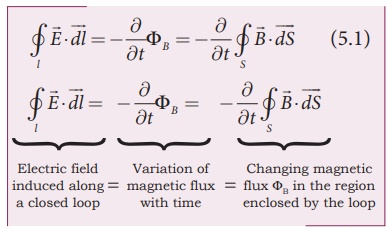
where ╬” is the magnetic
flux and Ōłé/Ōłét is the partial derivative with respect to time. Equation (5.1)
means that the electric field ![]() is induced along a closed
loop by the changing magnetic flux ╬”B in the region encircled
by the loop. Now the question asked by James Clerk Maxwell is ŌĆśIs converse of
this statement true?ŌĆÖ Answer is ŌĆśyesŌĆÖ. He showed that the change in electric
field also produces magnetic field which is
is induced along a closed
loop by the changing magnetic flux ╬”B in the region encircled
by the loop. Now the question asked by James Clerk Maxwell is ŌĆśIs converse of
this statement true?ŌĆÖ Answer is ŌĆśyesŌĆÖ. He showed that the change in electric
field also produces magnetic field which is
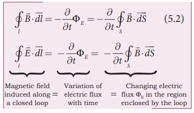
where ╬”B is
the electric flux. This is known as MaxwellŌĆÖs law of induction, which explains
that the magnetic field ![]() induced along a closed loop by
the changing electric flux ╬”E in the region encircled by that loop.
This in turn, explains the existence of radio waves, gamma rays, infrared rays,
etc.
induced along a closed loop by
the changing electric flux ╬”E in the region encircled by that loop.
This in turn, explains the existence of radio waves, gamma rays, infrared rays,
etc.
In order to understand
how the changing electric field produces magnetic field, let us consider a
situation of ŌĆścharging a parallel plate capacitorŌĆÖ shown in Figure 5.3 Assume
that the medium in between the capacitor plates is a non-conducting medium.
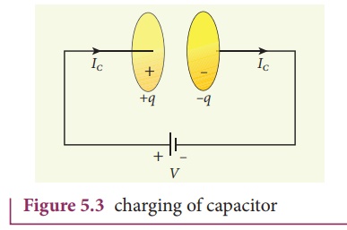
The electric current
passing through the wire is the conduction current IC. This current
generates magnetic field around the wire (refer Unit 3) connected across the
capacitor. Therefore, when a magnetic needle is kept near the wire, deflection
is observed. In order to compute the strength of magnetic field at a point, we
use Ampere's circuital law (from Unit 3) which states that ŌĆśthe line integral
of the magnetic field ![]() around any closed loop is equal to
┬Ąo times the net current I threading through the area enclosed by
the loopŌĆÖ. Ampere's law in equation form is
around any closed loop is equal to
┬Ąo times the net current I threading through the area enclosed by
the loopŌĆÖ. Ampere's law in equation form is
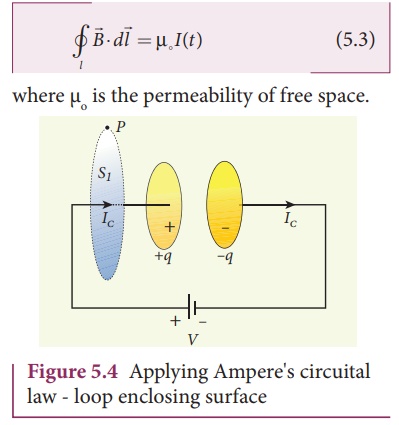
where ┬Ąo is the permeability of free space.
To calculate the
magnetic field at a point P near the wire as shown in Figure 5.4, let us draw
an amperian loop (circular loop) which encloses the surface S1
(circular surface). Therefore, using Ampere's circuital law (equation 5.3), we
get

where Ic is
the conduction current.
Suppose the same loop is
enclosed by balloon shaped surface S2 as shown in Figure 5.5. This
means that the boundaries of two surfaces S1 and S2 are
same but shape of the enclosing surfaces are different (first surface (S1)
is circular in shape and second one is balloon shaped surface (S2)).
As the AmpereŌĆÖs law applied for a given closed loop does not depend on shape of
the enclosing surface, the integrals will give the same answer. But by applying
AmpereŌĆÖs circuital law (equation 5.3), we get
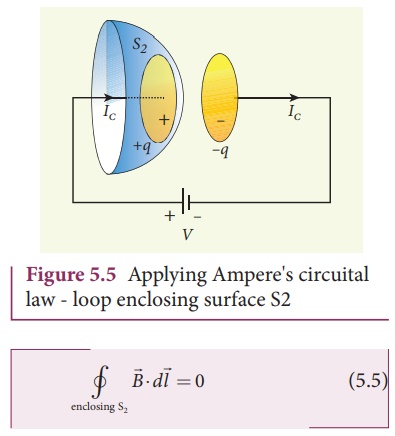
The right hand side of
equation is zero because the surface S2 no where touches the wire
carrying conduction current and further, there is no current in between the
plates of the capacitor (there is a discontinuity). So the magnetic field at a
point P is zero. Hence there is an inconsistency between equation (5.4) and
equation (5.5). J. C.Maxwell resolved this inconsistency as follows:
Due to external source
(battery or cell), the capacitor gets charged up because of current flowing
through the capacitor. This produces an increasing electric field between the
capacitor plates. So, there must be a current associated with the changing
electric field in between the capacitor plates. In other words, the time
varying electric flux (or time varying electric field) existing between the
plates of the capacitor also produces a current known as displacement current.
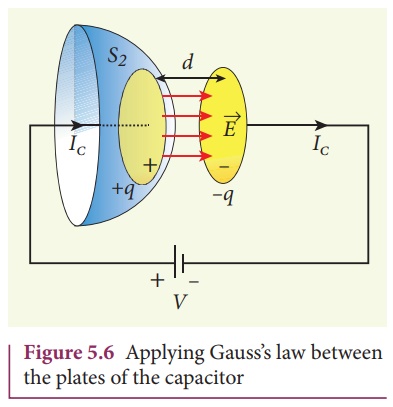
From GaussŌĆÖs law (refer
Unit 1), the electric flux between the plates of the capacitor (Figure 5.6) is

where A is the area of
the plates of capacitor.
The change in electric
flux is

where Id is
known as displacement current. The displacement current can be defined as
the current which comes into play in the region in which the electric field and
the electric flux are changing with time. In other words, whenever
the change in electric field takes place, displacement current is produced.
Maxwell modified Ampere's law as

where I = Ic
+ Id which means the total current enclosed by the surface is sum of
conduction current and displacement current. When a constant current is
applied, displacement current Id = 0 and hence Ic = I.
Between the plates, the conduction current Ic = 0 and hence Id
= I.
EXAMPLE 5.1
Consider a parallel
plate capacitor which is maintained at potential of 200 V. If the separation
distance between the plates of the capacitor and area of the plates are 1 and
20 cm2. Calculate the displacement current for the time in ┬Ąs.
Solution
Potential difference
between the plates of the capacitor, V = 200 V
The distance between the
plates,
d = 1 mm = 1 ├Ś 10-3
m
Area of the plates of
the capacitor,
A = 20 cm2 =
20 ├Ś 10-4 m2
Time is given in
micro-second, ┬Ąs = 10-6 s
Displacement current

But electric field, E =
V/d
Therefore,

= 35400 ├Ś10ŌłÆ7 = 3 .5 mA
Related Topics