Chapter: Civil : Construction Materials: Lime, Cement, Aggregates, Mortar
Concrete: Manufacturing Process

Concrete: Manufacturing Process
A good quality concrete is essentially a homogeneous mixture
of cement, coarse and fine aggregates and water which consolidates into a hard
mass due to chemical action between the cement and water. Each of the four
constituents has a specific function. The coarser aggregate acts as a filler.
The fine aggregate fills up the voids between the paste and the coarse
aggregate. The cement in conjunction with water acts as a binder. The mobility
of the mixture is aided by the cement paste, fines and nowadays, increasingly
by the use of admixtures.
Most of the properties of the
hardened concrete depend on the care exercised at every stage of the
manufacture of concrete. A rational proportioning of the ingredients of
concrete is the essence of the mix design. However, it may not guarantee of
having achieved the objective of th e quality concrete work. The aim of quality
control is to ensure the production of con crete of uniform strength from batch
to batch. This requires some rules to be followed in the various stages of
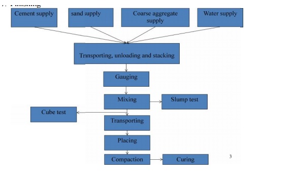
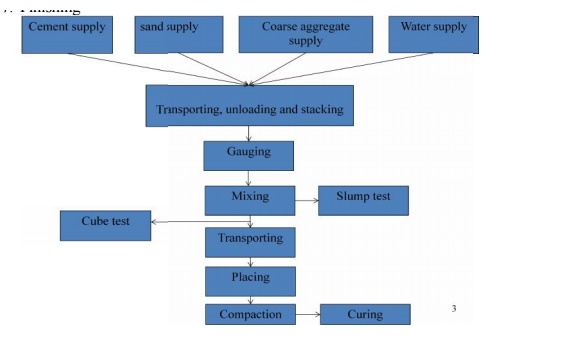
concrete production and are discussed as follows. The stages of concrete
production are:
1. Batching
or measureme nt of materials
2. Mixing
3. Transporting
4. Placing
5. Compacting
6.
Curing
7.
Finishing

Baching of Materials
For good quality co ncrete a
proper and accurate quantity of all th e ingredients should be used. The
aggregates, cement and water should be measured wit h an accuracy of ± 3 per
cent of batch quan tity and the admixtures by 5 per cent of the ba tch quantity.
There are two prevalent meethods of batching materials, the volume batc hing
and the weigh batching. The factors affecting the choice of batching method are
the size of job, required production rate, a nd required standards of batching
performance. For most important works weigh batch ing is recommended.
a) Volume
Batching
b) Weigh
Batching
Mixing
1. Hand
Mixing
2. Machine
Mixing
a) Tilting
Mixers
b) Non-tilting
Mixer
c) Reversing
Drum Mixer
d) Pan-type
or Stirring Mixer
e) Transit
Mixer
Charging the Mixer and Mixing Time
The order of feeding the ingredients into the mixer is as
follows:
About 25 per cent of water
required for mixing is first introduced into the mixer drum to prevent any
sticking of cement on the blades and bottom of the drum. Then the ingredients
are discharged through the skip. In the skip the sequence of loading should be
to add first half the coarse aggregate then half the fine aggregate and over
this total cement and then the balance aggregates. After discharging the
ingredients into the drum the balance water is introduced. The mixing time is
counted from the instant complete water is fed into the mixer.
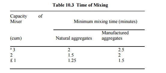
The speed of the mixers is
generally 15 to 20 rpm. For proper mixing, the number of revolutions per minute
required by the drum are 25 to 30. Time of mixing also depends on capacity of
mixer and is given in Table 10.3.

A poor quality of concrete is
obtained if the mixing time is reduced. On the other hand if the mixing time is
increased it is uneconomical. However, it is found that if the mixing time is
increased to 2 minutes the compressive strength of concrete produced is
enhanced and beyond this time the improvement in compressive strength is
insignificant. A prolonged mixing may cause segregation. Also, due to longer
mixing periods the water may get absorbed by the aggregates or evaporate
resulting in loss of workability and strength.
Transporting
Concrete should be transported to
the place of deposition at the earliest without the loss of homogeneity
obtained at the time of mixing. A maximum of 2 hours from the time of mixing is
permitted if trucks with agitator and 1 hour if trucks without agitators are
used for transporting concrete. Also it should be ensured that segregation does
not take place during transportation and placement. The methods adopted for
transporting concrete depend upon the size and importance of the job, the
distance of the deposition place from the mixing place, and the nature of the
terrain. Some of the methods of transporting concrete are as below:
a. Mortar
Pan
b. Wheel
Barrow
c. Chutes
d. Dumper
e. Bucket
and Ropeway
f. Belt
conveyor
g. Skip and
Hoist
h. Pumping
Placing
To achieve quality concrete it
should be placed with utmost care securing the homogeneity achieved during
mixing and the avoidance of segregation in transporting. Research has shown
that a delayed placing of concrete results in a gain in ultimate compressive
strength provided the concrete can be adequately compacted. For dry mixes in hot
weather delay of half to one hour is allowed whereas for wet mixes in cold
weather it may be several hours. The various situations in which concrete is
placed are discussed below.
Foundations
Concrete foundations for walls
and columns are provided below the ground surface. Before placing the concrete
in the foundation all the loose earth, roots of trees etc., are removed. If the
surface is found dry it is made wet so that earth does not absorb water from
concrete. On the other hand if the foundation bed is wet the water and mud is
removed and cement is sprinkled before placing concrete.
Beams, Columns, and Slabs
Before placing the concrete, the
forms must be examined for correct alignment. They should be adequately rigid
to withstand the weight of concrete and construction loads without undue
deformation. Forms should be light enough to avoid any loss of mortar resulting
in honeycombed concrete. The insides of the forms should be cleaned and oiled
before use to avoid any sticking of concrete with the forms and making their
stripping off difficult.
Concrete should not be dropped
but placed in position to prevent segregation. It should be dropped vertically
from as small height as possible. It should be placed at one point in the
formwork and allowed to flow side ways to take care of honeycombing.
Laitance formation should be
avoided. It can be checked by restricting thickness of layer of concrete by 150-300 mm
for R.C.C work. Laitance, however, if formed must be removed before placing the
next layer of concrete. Several such layers form a lift, provided they follow
one another quickly enough to avoid cold joints. The surface of the previous
lift is kept rough and all the laitance removed before placing the next lift.
The reinforcement should be
checked for tightness and clean surface. The loose rust or scales if any, are
removed by wire brush. Paint, oil or grease if found should be removed. The
minimum cover for reinforcement should be checked before concreting.
Mass Concreting
When the concrete is to be laid
in mass as for raft foundation, dam, bridge, pier etc., concrete is placed in
layers of 350-450 mm thickness. Several such layers placed
in quick succession form a lift. Before placing the concrete in the next lift,
the surface of the previous lift is cleaned thoroughly with water jets and
scrubbing by wire brush. In case of dams, sand blasting is done.
The laitance and loose materials
are removed and cement slurry is applied. When the concrete is subjected to
lateral thrust, bond bars or bond stones are provided to form a
key between different layers.
Concreting Highways and Runways
Concrete is laid in bays for
highway, runway, or floor slabs. First the ground on which concrete is to be
laid is prepared and all the loose materials and grass etc., are removed. The
earth is wetted and compacted. The subgrades over which concrete is to be laid
should be properly compacted and damped to avoid any loss of moisture from
concrete. Concrete is then laid in alternate bays. This allows the concrete to
undergo sufficient shrinkage and cracks do not develop afterwards. Concrete is
not placed in heap at one place and then dragged, instead it is placed in
uniform thickness.
Concreting Underwater
Concrete may be placed underwater
with the help of bottom dump buckets. The concrete is taken through the water
in water- tight bucket. On reaching the place of deposition the bottom of the
bucket is made to open and the concrete is dumped. In this process certain
amount of cement is washed away causing a reduction in strength of concrete.
Another way of concreting underwater is by filling cement bag with dry or
semi-dry mix of cement and aggregates and lowering them to the place of
deposition. The draw back of this method is that the concrete will be full of
voids interspersed with purticible gunny bags.
The best method of placing
concrete underwater is by the use of termie pipe. The concrete is poured
into it through funnel. The bottom end of the pipe is closed with a thick
ploythene sheet, with the bottom end of the pipe at the place of deposition.
The concrete (slump 150-200 mm) is poured into funnel
till the whole pipe is filled with concrete. The pipe is slightly lifted and
given a jerk, the polythene sheet cover falls and concrete discharged. It
should be ensured that the end of pipe remains inside the concrete so that
water does not enter the pipe. The pipe is again filled with concrete through
funnel and the process repeated till the concrete level comes above the water
level. No compaction is required for underwater concrete as it gets compacted
by the hydrostatic pressure of water. Concrete can also be placed underwater
with the help of pipes and pumps.
Compaction
After concrete is placed at the
desired location, the next step in the process of concrete production is its
compaction. Compaction consolidates fresh concrete within the moulds or
frameworks and around embedded parts and reinforcement steel. Considerable
quantity of air is entrapped in concrete during its production and there is
possible partial segregation also. Both of these adversely affect the quality
of concrete. Compaction of the concrete is the process to get rid of the
entrapped air and voids, elimination of segregation occurred and to form a
homogeneous dense mass. It has been found that 5 per cent voids in hardened
concrete reduce the strength by over 30 per cent and 10 per cent voids reduce
the strength by over 50 per cent. Therefore, the density and consequently the
strength and durability of concrete largely depend upon the degree of
compaction. For maximum strength driest possible concrete should be compacted
100 per cent.
The voids increase the
permeability of concrete. Loss of impermeability creates easy passage of
moisture, oxygen, chlorides, and other aggressive chemicals into the concrete.
This causes rusting of steel and spalling (disintegration) of concrete i.e.,
loss of durability. Easy entry of sulphates from the environment causes
expansive reaction with the tricalcium aluminate (C3A) present in
cement. This causes disintegration of concrete and loss of durability. Entry of
carbon dioxide causes carbonation of concrete i.e., loss of alkalinity of
concrete or loss of the protective power that concrete gives to the
reinforcement or other steel embedded in it. Once the carbonation depth exceeds
the thickness of concrete cover to the embedded steel, steel becomes vulnerable
to the attack of moisture. This expedites rusting of steel as the protective
concrete cover remains no longer alkaline in nature.
Voids also reduce the contact
between embedded steel and concrete. This results in loss of bond strength of
reinforced concrete member and thus the member loses strength. Voids such as
honeycombs and blowholes on the exposed surface produce visual blemish.
Concrete surface is not good to look with all such blemishes. Concrete with
smooth and perfect, surface finish not only looks good but is also stronger and
more durable.
Compaction is achieved by
imparting external work over the concrete to overcome the internal friction
between the particles forming the concrete, between concrete and reinforcement
and between concrete and forms and by reducing the air voids to a minimum. The
compaction of concrete can be achieved by the following methods.
1. Hand
Compaction
2. Compaction
by Vibration
a. Needle
Vibrator:
b. Formwork
Vibrator
3. Compaction
by Spinning
4. Compaction
by Jolting
5. Compaction
by Rolling
Curing
Cement gains strength and
hardness because of the chemical action between cement and water. This chemical
reaction requires moisture, favourable temperature and time referred to as the
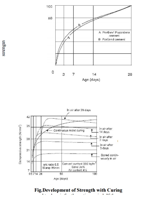
curing period. The variation of compressive strength with curing period is
shown in Fig. 10.11 (a, b). Curing of freshly placed concrete is very important
for optimum strength and durability. The major part of the strength in the
initial period is contributed by the clinker compound C3S and partly
by C2S, and is completed in about three weeks. The later strength
contributed by C2S is
gradual and takes long time. As such sufficient water should be made available
to concrete to allow it to gain full strength. The process of keeping concrete
damp for this purpose is known as curing. The object is to prevent the loss
of moisture from concrete due to
evaporation or any other reason,
supply additional moisture or heat and moisture to accelerate the gain of
strength. Curing must be done for at least three weeks and in no case for less
than ten days.
Approximately 14 litres of water
is required to hydrate each bag of cement. Soon after the concrete is placed,
the increase in strength is very rapid (3 to 7 days) and continues slowly
thereafter for an indefinite period. Concrete moist cured for 7 days is about
50 per cent stronger than that which is exposed to dry air for the entire
period. If the concrete is kept damp for one month, the strength is about
double than that of concrete exposed only to dry air.

Methods of Curing
Concrete may be kept moist by a
number of ways. The methods consist in either supplying additional moisture to
concrete during early hardening period by ponding, spraying, sprinkling, etc.
or by preventing loss of moisture from concrete by sealing the surface of
concrete by membrane formed by curing compounds. Following are some of the
prevelent methods of curing.
1. Water
Curing
2. Steam
Curing
3. Curing by
Infra Red Radiation:
4. Electrical
Curing
5. Chemical
Curing:
Finishing
Concrete is basically used
because of its high compressive strength. However, the finish of the ultimate
product is not that pleasant. In past couple of decades efforts have been made
to develop surface finishes to give a better appearance to concrete surfaces
and are as follows.
1. Formwork
Finishes
2. Surface
Treatments
3. Applied
Finishes
Related Topics