Chapter: Embedded Systems Design : Interrupts and exceptions
MC68000 interrupts
MC68000 interrupts
The MC68000 interrupt and exception processing is based on using an
external stack to store the processor’s context informa-tion. This is very
common and similar methods are provided on the 80x86 family and many of the
small 8 bit microcontrollers.
Seven interrupt levels are supported and are encoded onto three
interrupt pins IP0–IP2. With all three signals high, no exter-nal interrupt is
requested. With all three asserted, a non-maskable level 7 interrupt is
generated. Levels 1–6, generated by other combinations, can be internally
masked by writing to the appro-priate bits within the status register.
The interrupt cycle is started by a peripheral generating an interrupt.
This is usually encoded using a LS148 seven to three priority encoder. This
converts seven external pins into a 3 bit binary code. The appropriate code
sequence is generated and drives the interrupt pins. The processor samples the
levels and requires the levels to remain constant to be recognised. It is
recommended that the interrupt level remains asserted until its interrupt
acknowledgement cycle commences to ensure recognition.
Once the processor has recognised the interrupt, it waits until the
current instruction has been completed and starts an interrupt acknowledgement
cycle. This starts an external bus cycle with all three function code pins
driven high to indicate an interrupt acknowledgement cycle.
The interrupt level being acknowledged is placed on ad-dress bus bits
A1–A3 to allow external circuitry to identify which level is being
acknowledged. This is essential when one or more interrupt requests are
pending. The system now has a choice over which way it will respond:
•
If the peripheral can generate an
8 bit vector number, this is placed on the lower byte of the address bus and
DTACK* asserted. The vector number is read and the cycle com-pleted. This
vector number then selects the address and subsequent software handler from the
vector table.
•
If the peripheral cannot generate
a vector, it can assert VPA* and the processor will terminate the cycle using
the M6800 interface. It will select the specific interrupt vector allocated to
the specific interrupt level. This method is called auto-vectoring.
To prevent an interrupt request generating multiple ac-knowledgements,
the internal interrupt mask is raised to the interrupt level, effectively
masking any further requests. Only if a higher level interrupt occurs will the
processor nest its interrupt service routines. The interrupt service routine
must clear the interrupt source and thus remove the request before returning to
normal execution. If another interrupt is pending from a different source, it
can be recognised and cause another acknowledgement to occur.
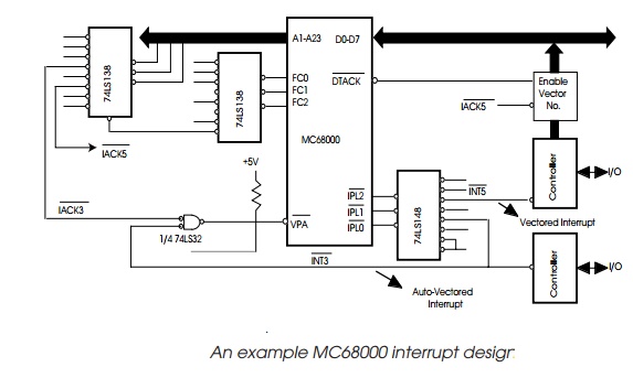
A typical circuit is shown. Here, level 5 has been allocated as a
vectored interrupt and level 3 auto-vectored. The VPA* signal is gated with the
level 3 interrupt to allow level 3 to be used with vectored or auto-vectored
sources in future designs.
Related Topics