Chapter: Basic Electrical and electronics : Electric Circuits and Measurements
Electrical Instruments and Classification of instruments
Measuring Instruments
Classification of instruments
(i).
Depending on the quality measured
Depending on the quality measured
Voltmeter
Ammeter
Energy
meter
Ohm meter
Depending on the different principles used for
their working
Moving
Iron type
Moving
coil type
Dynamometer
type
Induction
type
Depending on how the quantity is measured
Deflecting
type
Integrating
type
Recording
type
Deflecting Torque
The
deflecting torque moves the moving system and the pointer from the zero
position. The deflecting torque can be obtained through magnetic, thermal,
electromagnetic or electro dynamic effects
Controlling torque
The
controlling torque acts in a direction opposite to that of deflecting torque.
When the controlling torque (TC) and the deflecting torque (TD) are numerically
equal the pointer takes a definite position. In the absence of TC the pointer
would deflect to maximum position irrespective of the quantity to be measured.
Moreover TC also helps in bringing the moving system to zero position when the
instrument is disconnected from the circuit. The controlling torque is obtained
through spring control and gravity control
Spring Control:
The
arrangement for spring control consists of two phosphor bronze spiral hair
springs attached to a moving system. The springs are made of materials which
(i). are not affected by fatigue. (ii). Have low temp-coefficient of resistance
(iii). Have low specific resistance (iv). Are non-magnetic
As the
pointer deflects the springs get twisted in the opposite direction. The
combined twist produces the necessary controlling torque which is proportional
to angle of deflection of moving system θ. If we consider a permanent magnet
moving coil meter with spring control system the deflecting torque will be
proportional to the current passing through it and the controlling torque will
be proportional to the angle of deflection
Thus TD
α I
TC
α θ
Since TD
= TC
We have θ
α I
Thus the
spring controlled instruments having uniform scale
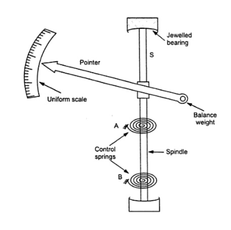
Gravity control
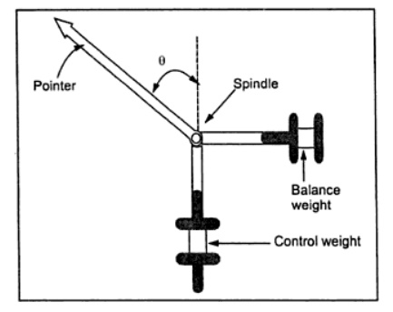
In
gravity controlled instruments, as shown in Fig. 12.2 (a) a small adjustable
weight is attached to the spindle of the moving system such that the deflecting
torque produced by the instrument has to act against the action of gravity.
Thus a controlling torque is obtained. This weight is called the control weight.
Another adjustable weight is also attached is the moving system for zero
adjustment and balancing purpose. This weight is called Balance weight.
When the
control weight is in vertical position as shown in Fig. 12.2 (a), the
controlling torque is zero and hence the pointer must read zero. However, if
the deflecting torque lifts the controlling weight from position A to B as
shown in Fig.12.2 (b) such that the spindle rotates by an angle θ, then due to
gravity a restoring (or controlling) torque is exterted on the moving system.
The
controlling (or restoring) torque, Tc , is given by
Tc = Wl
sin θ = k g sin θ where W is the control weight;
l is the
distance of the control weight from the axis of rotation of the moving system;
and k g is the gravity constant.
Equation
shows the controlling torque can be varied quite simply by adjustment of the
position of the control weight upon the arm which carries it. Again, if the
deflecting torque is directly proportional to the current,
i.e., Td
= kI
We have
at the equilibrium position Td = Tc
kI = k g
sin θ
I = g k
sin θ / k
This
relation shows that current I is proportional to sin θ and not θ. Hence in
gravity controlled instruments the scale is not uniform. It is cramped for the
lower readings, instead of being uniformly divided, for the deflecting torque
assumed to be directly proportional to the quantity being measured.
Advantanges of Gravity Control
1. It is
cheap and not affected by temperature variations.
2. It does
not deteriorate with time.
3. It is
not subject to fatigue.
Disadvantages of Gravity Control
1. Since the
controlling torque is proportional to the sine of the angle of deflection, the
scale is not uniformly divided but cramped at its lower end.
2. It is not
suitable for use in portable instruments (in which spring control is always
preferred).
3. Gravity
control instruments must be used in vertical position so that the control
weight may operate and also must be leveled otherwise they will give zero
error. In view of these reasons, gravity control is not used for indicating
instruments in general and portable instruments in particular.
Damping Torque
We have
already seen that the moving system of the instrument will tend to move under
the action of the deflecting torque. But on account of the control torque, it
will try to occupy a position of rest when the two torques are equal and
opposite. However, due to inertia of the moving system, the pointer will not
come to rest immediately but oscillate about its final deflected position as
shown in Fig and takes appreciable time to come to steady state. To overcome
this difficulty a damping torque is to be developed by using a damping device
attached to the moving system.
The
damping torque is proportional to the speed of rotation of the moving system,
that is Tv = kv d dt θ
where kv
= damping torque constant
d dt θ =
speed of rotation of the moving system
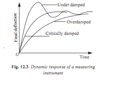
Depending
upon the degree of damping introduced in the moving system, the instrument may
have any one of the following conditions as depicted in Fig.
1. Under
damped condition: The response is oscillatory
2. Over
damped condition: The response is sluggish and it rises very slowly from its
zero position to final position.
3. Critically
damped condition: When the response settles quickly without any oscillation,
the system is said to be critically damped.
In
practice, the best response is slightly obtained when the damping is below the
critical value i.e., the instrument is slightly under damped.
The
damping torque is produced by the following methods: Air Friction Damping &
Fluid friction damping
Air Friction Damping
In this
type of damping a light vane or vanes having considerable area is attached to
the moving system to develop a frictional force opposing the motion by reason
of the air they displace. Two methods of damping by air friction are depicted
in Fig.
The
arrangement shown in Fig consists of a light aluminum vane which moves in a
quadrant (sector) shaped air chamber. The chamber also carries a cover plate at
the top. The vane is mounted on the spindle of the moving system. The aluminum
vane should not touch the air-chamber walls otherwise a serious error in the
deflection of the instrument will be introduced. Now, with the motion, the vane
displaces air and thereby a damping force is created on the vane that produces
a torque (damping) on the spindle. When the movement is quicker the damping
force is greater; when the spindle is at rest, the damping force is zero.
The
arrangement of Fig. consists of a light aluminum piston which is attached to
the moving system. This piston moves in a fixed chamber which is closed at one
end. Either circular or rectangular chamber may be used. The clearance (or gap)
between the piston and chamber walls should be uniform throughout and as small
as possible. When the piston moves rapidly into the chamber the air in the
closed space is compressed and the pressure of air thus developed opposes the
motion of the piston and thereby the whole moving system. If the piston is
moving out of the chamber, rapidly, the pressure in the closed space falls and
the pressure on the open side of the piston is greater than that on the
opposite side. Motion is thus again opposed. With this damping system care must
be taken to ensure that the arm carrying the piston should not touch the sides
of the chamber during its movement. The friction which otherwise would occur
may introduce a serious error in the deflection.
The air
friction damping is very simple and cheap. But care must be taken to ensure
that the piston is not bent or twisted. This method is used in moving iron and
hot wire instruments.
Fluid Friction Damping
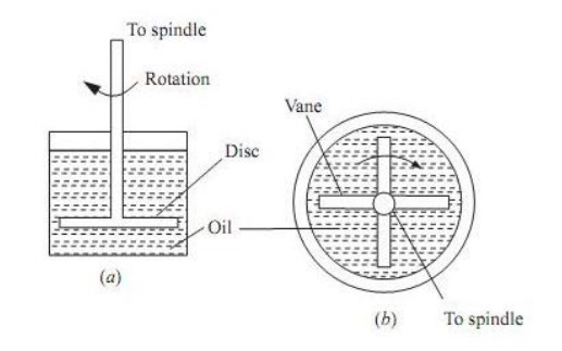
This form
is damping is similar to air friction damping. The action is the same as in the
air friction damping. Mineral oil is used in place of air and as the viscosity
of oil is greater, the damping force is also much greater. The vane attached to
the spindle is arranged to move in the damping oil. It is rarely used in
commercial type instruments. The oil used must fulfill the following
requirements. It should not evaporate quickly . It should not have any
corrosive effect on metals. Its viscosity should not change appreciably with
temperature. It should be good insulator.
Advantages of Fluid Friction Damping
1. The oil
used for damping can also be used for insulation purpose in some forms of
instruments which are submerged in oil.
2. The
clearance between the vanes and oil chamber is not as critical as with the air
friction clamping system.
3. This
method is suitable for use with instruments such as electrostatic type where
the movement is suspended rather than pivoted.
4. Due to
the up thrust of oil, the loads on bearings or suspension system is reduced
thereby the reducing the frictional errors.
Disadvantages of Fluid Friction Damping
1. The
instruments with this type of damping must be kept always in a vertical
position.
2. It is
difficult to keep the instrument clean due to leakage of oil.
It is not
suitable for portable instruments. The fluid friction damping can be used for
laboratory type electrostatic instruments.
Eddy current damping
Eddy
Current Damping
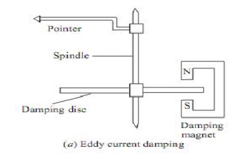
Eddy
current damping is the most efficient form of damping. The essential components
in this type of damping are a permanent magnet; and a light conducting disc
usually of alumninum. When a sheet of conducting material moves in a magnetic
field so as to cut through lines of force, eddy currents are set up in it and a
force exists between these currents and the magnetic field, which is always in
the direction opposing the motion. \
This
force is proportional to the magnitude of the current, and to the strength of
field. The former is proportional to the velocity of movement of the conductor,
and thus, if the magnetic field is constant, the damping force is proportional
to the velocity of the moving system and is zero when there is no movement of
the system.
Related Topics