Chapter: Digital Logic Circuits : Combinational Circuits
Demultiplexers
Demultiplexers
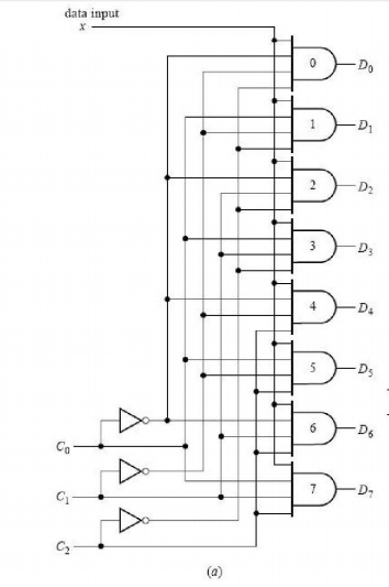
The demultiplexer shown there is a single-input,
multiple-output circuit. However, in addition to the data input, there must be
other inputs to control the transmission of the data to the appropriate data
output line at any given time. Such a demultiplexer circuit having eight output
lines is shown in Figure 16a. It is instructive to compare this demultiplexer
circuit with the multiplexer circuit in Figure 13. For the same number of
control (select) inputs, there are the same number of AND gates. But now each
AND gate output is a circuit output. Rather than each gate having its own
separate data input, the single data line now forms one of the inputs to each
AND gate, the other AND inputs being control inputs.
When the word formed by the control inputs
C2C1C0 is the binary equivalent of decimal k, then the data input x is routed
to output Dk. Viewed in another way, for a demultiplexer with n control inputs,
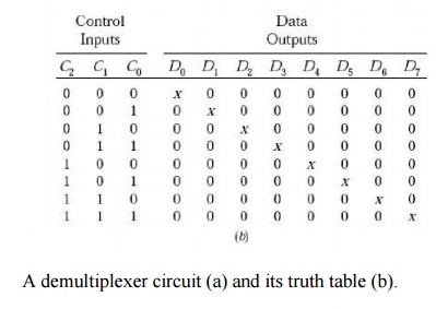
each AND gate output corresponds to a minterm of n variables. For a given
combination of control inputs, only one minterm can take on the value 1; the
data input is routed to the AND gate corresponding to this minterm. For
example, the logical expression for the output D3 is xC2'C1C0. Hence, when
C2C1C0 = 011, then D3 = x and all other Di are 0. The complete truth table for
the eight-output demultiplexer.
Related Topics