Chapter: Special Electrical Machines : Permanent Magnet Synchronous Motor
Vector Control of BLPM SNW Motor
VECTOR CONTROL OF BLPM SNW MOTOR
Electromagnetic
torque in any electrical machine is developed due to the interaction of current
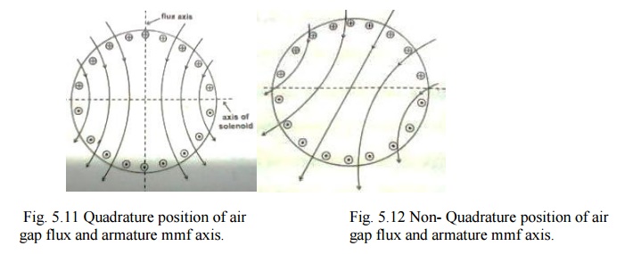
carrying armature conductors with the air gap flux. Consider a two machine
whose armature conductor currents and air gap flux are as shown in fig. 5.12.
Here the flux is in quadrature with the armature mmf axis.
Each and
every armature conductor experiences a force which contributes the torque. The
torque contributed by various armature conductors have the same direction even
through their magnitude may vary. It is observed that the steady state and
dynamic (behaviors) performance of a most of such an arrangement are better.
Consider
a second case wherein the armature conductor current distribution and air gap
flux distribution are as shown in fig. 6.26. In this case the angle between the
axis of the air gap flux and the armature mmf axis is different from 90° elec.
In this
case also each and every armature conductor experiences a force and contributes
to the torque. But in this case the direction of the torque experienced by the
conductors is not the same. Since conduction develops torque in one direction
while the others develop in the opposite direction. As a result, the resultant
torque gets reduced; consequently it is observed that both the steady state and
dynamic performance of such a motor is poorer.
For a
BLPM motor to have better steady state and dynamic performance, it is essential
that the armature mmf axis and the axis of PM are to be in quadrature for all
operating condition.
1. Principle of vector control
BLPM SNW
motor is usually employed for variable speed applications. For this we keep V/f
constant and vary V and f to get the desired speed and torque.
From the
theory of BLPM SNW motor it is known that as the speed is varied from a very
low value upto the corner frequency, the desired operating point of current is
such that Id =0 and I is along the q-axis. Such a condition can be
achieved by suitably controlling the voltage by PWM technique after adjusting
the frequency to a desired value.
When the
frequency is more than the corner frequency it is not possible to make Id
=0, due to the voltage constraints. In such a case a better operating point for
current is obtained with minimum Id value after satisfying the
voltage constraints. Controlling BLPM SNW motor taking into consideration the
above mentioned aspects is known as ―vector Control‖ of BLPM SNW motor.
2. Schematic Diagram of Vector
Control
The
schematic block diagram of vector control is as shown in figure 5.13Knowing the
value of the desired torque and speed and also the parameters and the voltage
to which the motor is subjected to, it is possible to complete the values of id
.ref and iq .ref for the desired dynamic and steady state
performance.
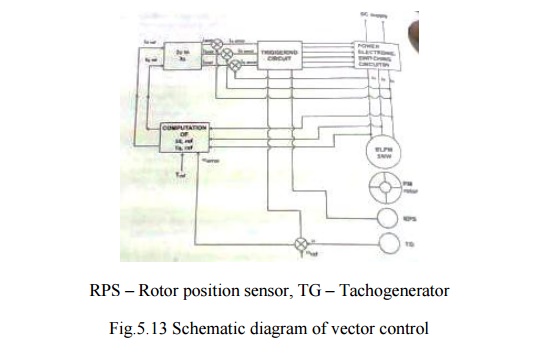
The
reference values of id and iq are transformed into
reference values of currents namely ia ref, ib ref and ic
ref. These currents are compared with the actual currents and the error values
actuate the triggering circuitry which is also influenced by the rotor position
sensor and speed. Thus the vector control of BLPM SNW motor is achieved.
Related Topics