Chapter: Special Electrical Machines : Permanent Magnet Synchronous Motor
Construction and Principle of Operation - Permanent Magnet Synchronous Motor
CONSTRUCTION AND PRINCIPLE OF
OPERATION
Permanent
magnet synchronous machines generally have same operating and performance
characteristics as synchronous machines. A permanent magnet machine can have a
configuration almost identical to that of the conventional synchronous machines
with absence of slip rings and a field winding.
Construction
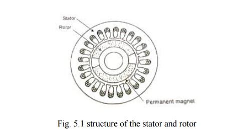
Fig. 5.1
shows a cross section of simple permanent magnet synchronous machines. It
consists of the stationary member of the machine called stator. Stator
laminations for axial air gap machines are often formed by winding continuous
strips of soft steel. Various parts of the laminations are the teeth slots
which contain the armature windings. Yoke completes the magnetic path.
Lamination thickness depends upon the frequency of the armature source voltage
and cost.
Armature
windings are generally double layer (two coil side per slot) and lap wound.
Individual coils are connected together to form phasor groups. Phasor groups
are connected together in series/parallel combinations to form star, delta, two
phase (or) single windings.
AC
windings are generally short pitched to reduce harmonic voltage generated in
the windings.
Coils,
phase groups and phases must be insulated from each other in the end-turn
regions and the required dielectric strength of the insulation will depend upon
the voltage ratings of the machines.
In a
permanent magnet machines the air gap serves an role in that its length largely
determines the operating point of the permanent magnet in the no-load operating
condition of the machines .Also longer air gaps reduce machines windage losses.
The
permanent magnets form the poles equivalent to the wound field pole of
conventional synchronous machines. Permanent magnet poles are inherently
―salient‖ and there is no equivalent to the cylindrical rotor pole
configurations used in many convectional synchronous machines.
Many
permanent magnet synchronous machines may be cylindrical or ―smooth rotor‖
physically but electrically the magnet is still equivalent to a salient pole
structure. Some of the PMSM rotors have the permanent magnets directly facing
the air gap as in fig. 5.2.
Rotor
yoke is the magnetic portion of the rotor to provide a return path for the
permanent magnets and also provide structural support. The yoke is often a part
of the pole structure
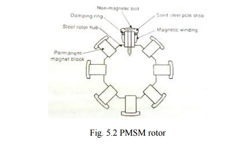
Damper
winding is the typical cage arrangement of conducting bars, similar to
induction motor rotor bars and to damper bars used on many other types of
synchronous machines. It is not essential for all permanent magnet synchronous
machines applications, but is found in most machines used in power
applications.
The main
purpose is to dampen the oscillations about synchronous speed, but the bars are
also used to start synchronous motors in many applications.
The
design and assembly of damper bars in permanent magnet machines are similar to
the other types of synchronous machines.
Synchronous
machines are classified according to their rotor configuration. There are four
general types of rotors in permanent magnet synchronous machines. They are
1. Peripheral
rotor
2. Interior
rotor
3. Claw pole
or lundell rotor.
4. Transverse
rotor.
v Peripheral rotor
The permanent magnets are located on the rotor
periphery and permanent magnet flux is radial.
v Interior rotor
The
permanent magnets are located on the interior of the rotor and flux is
generally radial.
v Claw pole or Lund ell
The permanent magnets are generally disc shaped and
magnetized axially. Long soft iron extensions emanate axially from periphery of
the discs like claws or Lund ell poles. There is set of equally spaced claws on
each disc which alternate with each other forming alternate north and south
poles.
v
Transverse rotor
In this type the permanent magnets are generally
between soft iron poles and the permanent magnet flux is circumferential. In
this soft iron poles at as damper bars. Magnetically this configuration is
similar to a reluctance machine rotor, since the permeability of the permanent
magnet is very low, almost the same as that of a non-magnetic material.
Therefore, reluctance torque as well as torque resulting from the permanent
magnet flux is developed.
Thus BLPM sine waves (SNW) motor is construction
wise the same as that of BLPM square wave (SQW) motor. The armature winding and
the shape of the permanent magnet are so designed that flux density
distribution of the air gap is sinusoidal(i.e.) .The magnetic field setup by
the permanent magnet in the air gap is sinusoidal
Related Topics