Chapter: Special Electrical Machines : Permanent Magnet Synchronous Motor
Torque Equation of BLPM Sine Wave Motor
TORQUE EQUATION OF BLPM SINE WAVE
MOTOR
1. Ampere conductor density
distribution

2. Torque equation of an ideal BLPM sine wave motor
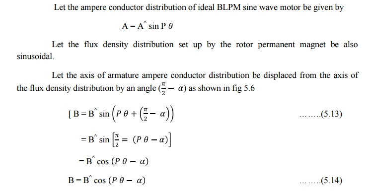
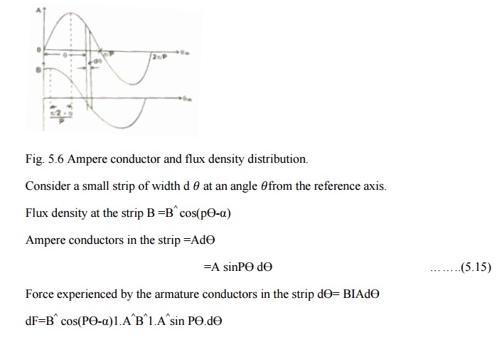
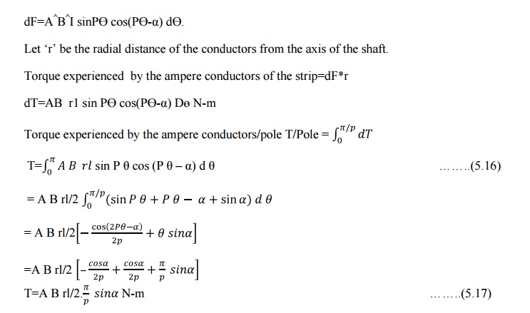
Let the
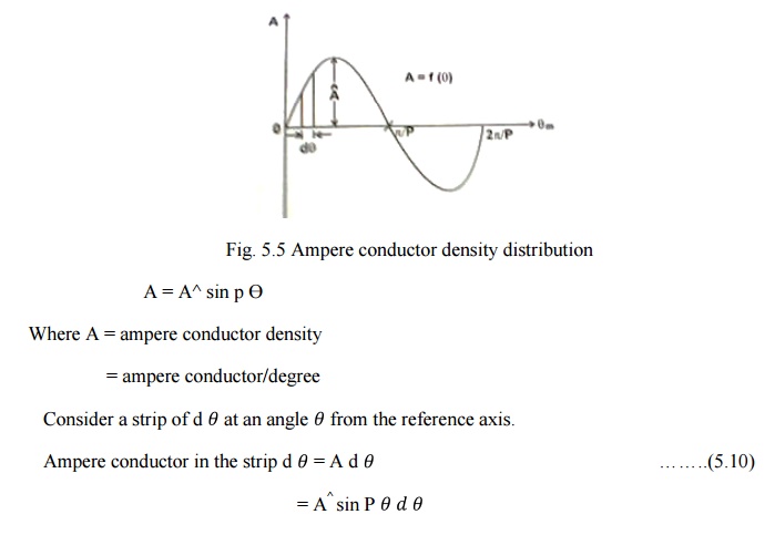
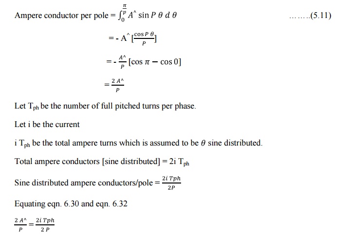
fig. 5.5 shows the ampere conductor density distribution in the air gap due to
the current carrying armature winding be sinusoidal distributed in the airgap
space.

As the
armature conductors are located in stator of the BLPM SNW motor, the rotor
experiences an equal and opposite torque.
Torque
experienced by the rotor
= Torque
developed by the rotor

Β is
known as power angle or torque angle. T= π A B rl sin β in an ideal motor.
Consider
the case of an armature winding which has three phases. Further the winding
consists of short chorded coils and the coils of a phase group are distributed.
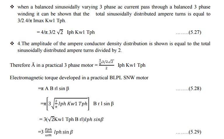
The 3 phase armature winding carries a balanced 3 phase ac current which are
sinusoidally varying. The various phase windings are ph a, ph b and ph c.
The axis
of phase winding are displaced by 2π/3p mechanical radians or 2π/3 elec.
Radians.
The
current in the winding are also balanced. An armature winding is said to be
balanced if all the three phase winding are exactly identical in all respects
but there axes are mutually displaced by 2π/3p mech radians apart.
A three
phase armature current is said to be balanced when the 3 phase currents are
exactly equal but mutually displaced in phase by 120 degree.

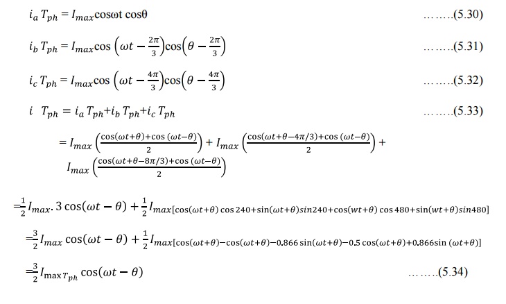
When the
3 phase ac current passes through the 3 phase balanced winding it sets up an
armature mmf in the air gap.
Space
distribution of the fundamental component of armature ampere conductors can be
written as.

3. Torque developed in a practical BLPM SNW motor:
v Ampere
turn distribution of a phase winding consisting of full pitched coil is
rectangular of amplitude I T ph. But the fundamental component of this
distribution is the fundamental component of this distribution is 4/πi Tph.
v In a
practical motor, the armature turns are short chorded and distributed .Further
they may be accomonadated in skewed slots. In such a case for getting
fundamental component of ampere turns distribution the turns per phase is
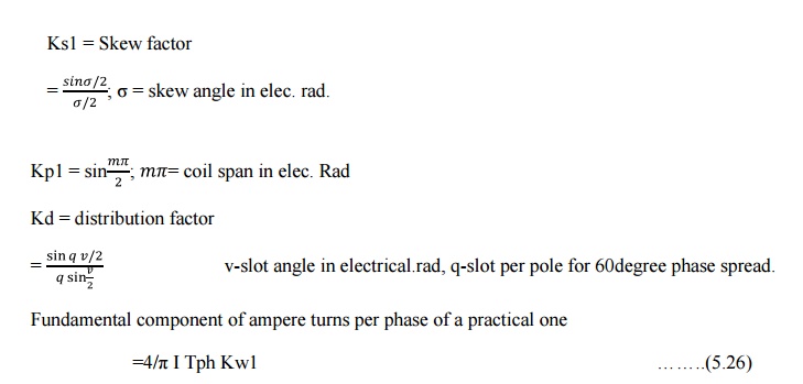
modified as Kw1 Tph where Kw1 is winding factor which is equal to Ks1 Kp1 Kd1
Ks1 =
Skew factor
Properties
of 'A‘ ( Ampere conductor density);
v Ampere
conductor density is sinusoidally distributed in space with amplitude Â. This
distribution has 2p poles (i.e) same as the rotor permanent magnetic field.
v The
ampere conductor distribution revolves in air gap with uniform angular velocity
ώm rad /sec .or ώelec.rad/sec.(Ns rpm). This is the same speed as
that of rotor magnetic field.
v The
direction of rotation of armature ampere conductor distribution is same as that
of rotor. This is achieved by suitably triggering the electronic circuit from
the signals obtained from rotor position sensor.
v 4. The
relative angular velocity between sine distributed permanent magnetic field and
sine distributed armature ampere conductor density field is 0. Under such
condition it has been
shown an electromagnetic torque is developed whose
magnitude is proportional to sin β. β-torque angle or power angle.
Angle
between the axes of the two fields is π/2-α and β=-α Torque developed by the
motor = 3EphIphsinβ/ώmN-m
Where
ώm-angular velocity in rad/sec.
ώm=2πNs/60 where
NS is in rpm
T=60/2πNs
(3EphIphsinβ)
=3EphIphsinβ syn.watts. 1 syn.watt=60/2πNs N-m
It is a
machine dependent conversion factor
Related Topics