Chapter: Special Electrical Machines : Permanent Magnet Synchronous Motor
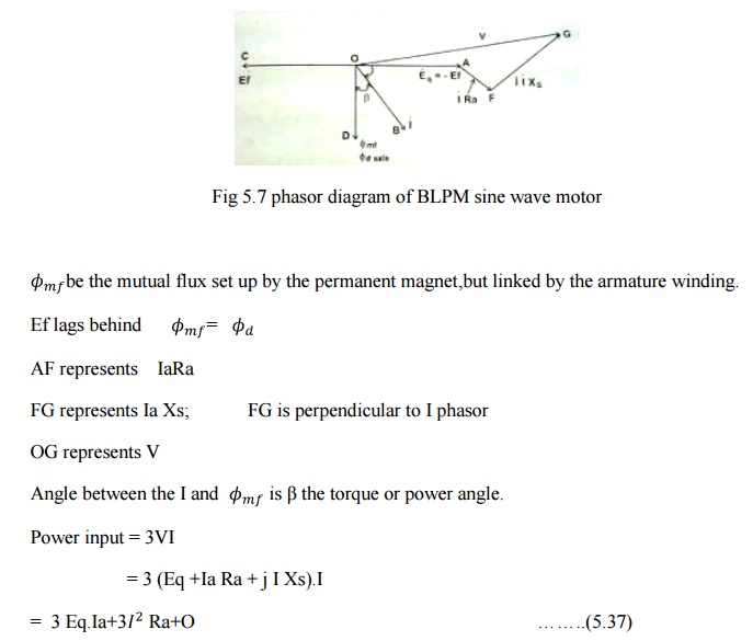
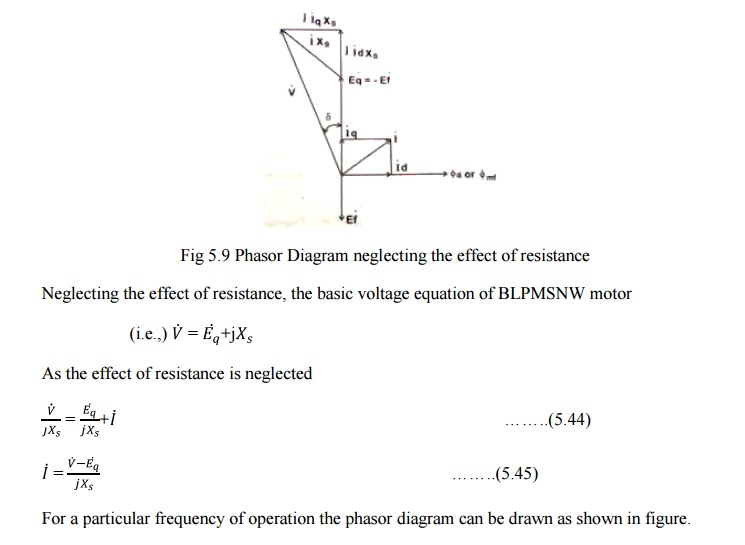
Phasor Diagram of a Brushless PM SNW or BLPB Synchronous Motor
PHASOR DIAGRAM OF A BRUSHLESS PM
SNW OR BLPB SYNCHRONOUS MOTOR:
Consider a BLPM SNW motor, the stator carries a balanced 3ϕ winding .this winding is connected to a dc supply through an electronic commutator whose switching action is influenced by the signal obtained from the rotor position sensor.
Under
steady state operating condition, the voltage available at the input terminals
of the armature winding is assumed to be sinusoidally varying three phase
balanced voltage. The electronic commutator acts as an ideal inverter whose
frequency is influenced by the rotor speed. Under this condition a revolving
magnetic field is set up in the air gap which is sinusoidally distributed in
space, having a number of poles is equal to the rotor. It rotates in air gap in
the same direction as that of rotor and a speed eq1ual to the aped of the rotor
Rotor
carries a permanent magnet. Its flux density is sine distributed. It also
revolved in the air gap with as particular apreed
It is
assumed that the motor acts as a balanced 3ϕ system. Therefore it is sufficient
to draw the phasor diagram for only one phase. The armature winding circuit is
influenced by the following emfs.
1. V - supply voltage per phase across each winding
of the armature .
The magnitude of this voltage depends upon dc
voltage and switching techniques adopted .
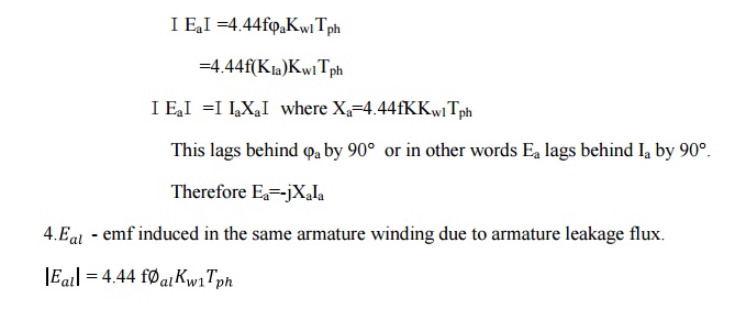
2. Ef
- emf induced in the armature winding
per phase due to sinusoidally varying
permanent
magnetic field flux. Magnitude of Ef=4.44ϕmfKw1Tph=Ӏ EfӀ
As per Faradays law of electromagnetic induction,
this emf lags behind ϕmf-permanent magnet flux enclosed by armature
phase winding by 90°.
3. Ea
- emf induced in the armature phase winding due to the flux ϕa set
up by resultant armature mmf ϕ∞Ia

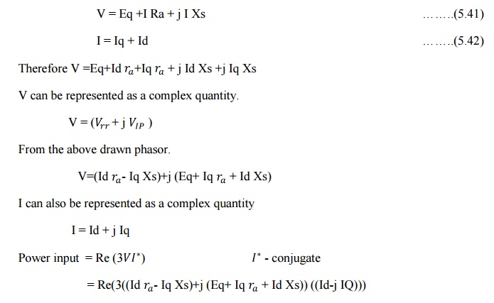
Further the current I phasor is resolved into two components Id and Iq
Id set up mmf
along the direct axis (or axis of the permanent magnet)
Iq sets
up mmf along quadrature axis (i,e) axis perpendicular to the axis of permanent
magnet.
Note:
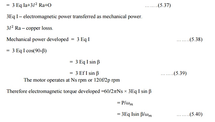
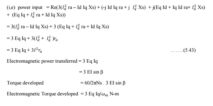
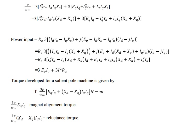
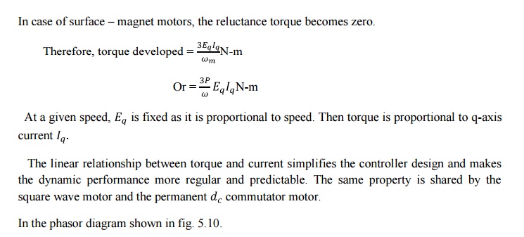
In case
of salient pole rotors the electromagnetic torque developed from the electrical
power. From eqn. (5.43)
Related Topics