Chapter: Special Electrical Machines : Permanent Magnet Synchronous Motor
Self Control of PMSM
SELF CONTROL OF PMSM
As the rotor speed changes the armature supply frequency is also change proportionally so that the armature field always moves (rotates) at the same speed as the rotor. The armature and rotor field move in synchronism for all operating points. Here accurate tracking of speed by frequency is realized with the help of rotor position sensor.
When the rotor makes certain predetermined angle with the axis of the armature phases the firing pulses to the converter feeding the motor is also change. The switches are fired at a frequency proportional to the motor speed. Thus the frequency of the voltage induced in the armature is proportional to the speed.
Self-control ensures that for all operating points the armature and rotor fields move exactly at the same speed. The torque angle is adjusted electronically hence there is an additional controllable parameter passing greater control of the motor behavior by changing the firing of the semi-conductor switches of an inverter.
The torque angle is said electronically hence the fundamental component of phase A needs Φf/β, it lies along the direct axis that rotates at a synchronous speed. The switches must be triggered by phase A current component when Φf axis is β electrical degrees behind the phase A axis. This is achieved by firing the switch when direct axis is δ+β behind axis of A as show shown in fig.
Self-control is applicable to all variable frequency converters, the frequency being determined by machine.
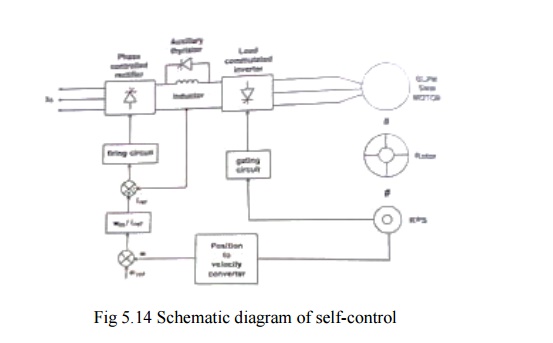
At high power levels the most common power converter configuration is the current fed DC link converter which is shown in fig. 5.14.
1. Inner current and outer speed loop
The phase controlled thyristor rectifier on the supply side of the DC link has the current regulating loop and operate as a control current source. The regulated DC current is delivered to the DC link inductor to the thyristor of load commutator inverter which supplies line current to the synchronous motor.
The inverter gating signals are under the control of shaft-position sensor giving a commutator less dc motor with armature current controlled. The thyristor of these inverters utilize load commutation because of the generated emf appearing at the armature. It is ensured by the over excitation of synchronous motor, so that it operates at leading power factor hence it reduces commutating circuitry, low losses and is applicable to power levels of several megawatts.
The shaft position is sensed by the position sensor. The shaft speed is obtained by converting the position information. This speed is compared with the reference speed signal which provides the speed error. This is the current reference signal for the linear current loop.
This reference current is compared with the sensed dc link current which provides control signals for the rectifier thyristor. The sensed shaft position is used as gating signal for inverter thyristor.
2. Commutation at low speed
Load commutation is ensured only at high speeds. Whereas at low speeds the emf generated is not sufficient for load commutation. The inverter can be commutated by supplying pulsating on and off dc link current. This technique produces large pulsating torque but this is not suitable for drives which require smooth torque at low speed.
The DC link current is pulsed by phase shifting the gate signal of the supply side converter from rectification to inversion and back again. When the current is zero the motor side converter is switched to a new conduction period and supply side converter is then turned on. Time required for the motor current to fall to zero can be significantly shortened by placing a shunt thyristor in parallel with a DC link inductor. When the current zero is needed the line side converter is phased back to inversion and the auxiliary thyristor is gated.
The DC link inductor is then short circuited and its current can supply freely without affecting the motor. When the line side converter is turned on the auxiliary thyristor is quickly blocked. This method of interruption of the motor current reduces the effect of pulsating torque.
3. Four Quadrant Operations
The drive characteristics are similar to those of a conventional DC motor drive. Motor speed can be increased to a certain base speed corresponding to the maximum voltage from the supply. Further, increase in speed is obtained by reducing the field current to give a field weakening region of operation.
Regenerative braking is accomplished by shifting the gate signal, so that machine side inverter acts as a rectifier and supply side rectifier as a inverter, hence the power is return to the ac utility network. The direction of rotation
Of the motor is also reversible by alternating the gate sequence of the motor side converter. Thus four quadrant operations are achieved, without additional circuitry.
Related Topics