Chapter: Satellite Communication : Space Segment and Satellite Link Design
TT&C Subsystem
TT&C
Subsystem
The
TT&C subsystem performs several routine functions aboard the spacecraft.
The telemetry, or telemetering, function could be interpreted as measurement at
a distance. Specifically, it refers to the overall oper- ation of generating an
electrical signal proportional to the quantity being measured and encoding and
transmitting this to a distant station, which for the satellite is one of the
earth stations.
Data
which are trans- mitted as telemetry signals include attitude information such
as that obtained from sun and earth sensors; environmental information such as
the magnetic field intensity and direction, the frequency of meteorite impact,
and so on; and spacecraft information such as temperatures, power supply
voltages, and stored-fuel pressure.
Telemetry
and command may be thought of as complementary func- tions. The telemetry
subsystem transmits information about the satellite to the earth station, while
the command subsystem receives command sig- nals from the earth station, often
in response to telemetered information. The command subsystem demodulates and,
if necessary, decodes the com- mand signals and routes these to the appropriate
equipment needed to exe- cute the necessary action.
Thus
attitude changes may be made, communication transponders switched in and out of
circuits, antennas redirected, and station-keeping maneuvers carried out on
command. It is clearly important to prevent unauthorized commands from being
received and decoded, and for this reason, the command signals are often
encrypted.
Encrypt
is derived from a Greek word kryptein, meaning to hide, and rep- resents the
process of concealing the command signals in a secure code. This differs from
the normal process of encoding which converts characters in the command signal
into a code suitable for transmission.
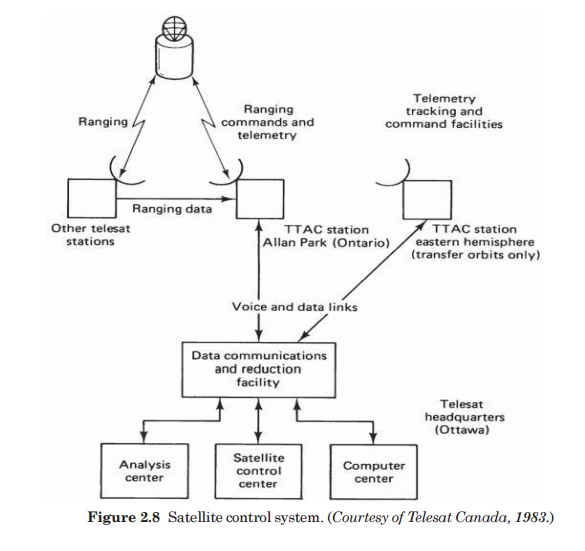
Tracking
of the satellite is accomplished by having the satellite trans- mit beacon
signals which are received at the TT&C earth stations.
Tracking
is obviously important during the transfer and drift orbital phases of the
satellite launch. Once it is on station, the position of a geo- stationary
satellite will tend to be shifted as a result of the various dis- turbing
forces, as described previously.
Therefore,
it is necessary to be able to track the satellite’s movement and send
correction signals as required.
1. Transponders:
A
transponder is the series of interconnected units which forms a single
communications channel between the receive and transmit antennas in a
communications satellite.
Some
of the units utilized by a transponder in a given channel may be common to a
number of transponders. Thus, although reference may be made to a specific
transponder, this must be thought of as an equipment channel rather than a
single item of equipment.
Before
describing in detail the various units of a transponder, the overall frequency
arrangement of a typical C-band communications satellite will be examined
briefly. The bandwidth allocated for C-band service is 500 MHz, and this is
divided into subbands, one transponder.
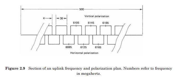
A
typical transponder bandwidth is 36 MHz, and allowing for a 4-MHz guardband
between transponders, 12 such transponders can be accommodated in the 500-MHz
bandwidth.
By
making use of polarization isolation, this number can be doubled.
Polarization isolation refers to the fact that carriers, which may be on the
same frequency but with opposite senses of polarization, can be isolated from
one another by receiving antennas matched to the incoming polarization.
With
linear polarization, vertically and horizontally polarized carriers can be separated in this way, and with circular polarization, left-hand circular and
right-hand circular polarizations can be separated.
Because
the carriers with opposite senses of polarization may overlap in frequency,
this technique is referred to as frequency reuse. Figure 2.9 shows part of the
frequency and polarization plan for a C-band communications satellite.
Frequency
reuse also may be achieved with spot-beam antennas, and these may be combined
with polarization reuse to provide an effective bandwidth of 2000 MHz from the
actual bandwidth of 500 MHz.
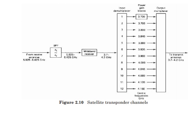
For
one of the polarization groups, Fig. 2.9 shows the channeling scheme for the 12
transponders in more detail. The incoming, or uplink, frequency range is 5.925
to 6.425 GHz.
The
frequency conversion shifts the carriers to the downlink frequency band, which
is also 500 MHz wide, extending from 3.7 to 4.2 GHz. At this point the signals
are channelized into frequency bands which represent the individual transponder
bandwidths.
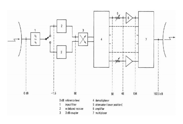
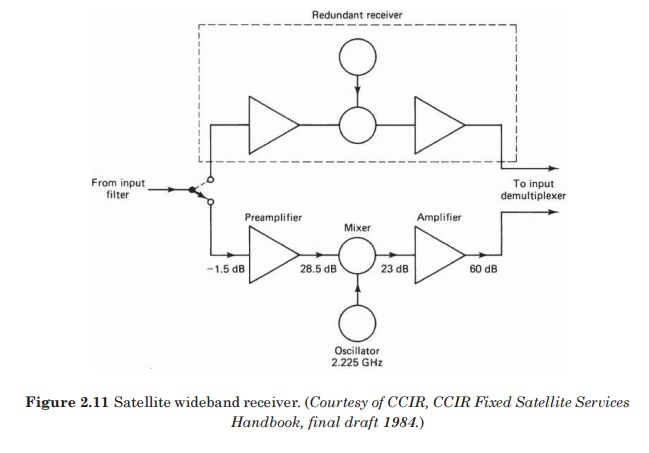
2. The wideband
receiver
The
wideband receiver is shown in more detail in Fig. 2.10. A duplicate receiver is
provided so that if one fails, the other is automatically switched in. The
combination is referred to as a redundant receiver, meaning that although two
are provided, only one is in use at a given time.
The
first stage in the receiver is a low-noise amplifier (LNA). This amplifier adds
little noise to the carrier being amplified, and at the same time it provides
sufficient amplification for the carrier to override the higher noise level
present in the following mixer stage.
involving
noise, it is usually more convenient to refer all noise levels to the LNA
input, where the total receiver noise may be expressed in terms of an
equivalent noise temperature.
In
a well-designed receiver, the equivalent noise temperature referred to the LNA
input is basically that of the LNA alone. The overall noise temperature must
take into account the noise added from the antenna, and these calculations are
presented in detail in Chap. 12. The equivalent noise temperature of a
satellite receiver may be on the order of a few hundred kelvins.
The
LNA feeds into a mixer stage, which also requires a local oscillator (LO)
signal for the frequency-conversion process.
With
advances in field-effect transistor (FET) technology, FET amplifiers, which
offer equal or better performance, are now available for both bands. Diode
mixer stages are used.
The
amplifier following the mixer may utilize bipolar junction transistors (BJTs)
at 4 GHz and FETs at 12 GHz, or FETs may in fact be used in both bands.
3. The input
demultiplexer
The
input demultiplexer separates the broadband input, covering the frequency range
3.7 to 4.2 GHz, into the transponder frequency channels.
This
provides greater frequency separation between adjacent channels in a group,
which reduces adjacent channel interference.
The
output from the receiver is fed to a power splitter, which in turn feeds the
two separate chains of circulators.
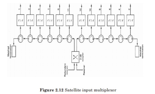
The
full broadband signal is transmitted along each chain, and the channelizing is
achieved by means of channel filters con- nected to each circulator, Each
filter has a bandwidth of 36 MHz and is tuned to the appropriate center
frequency, as shown in Fig. 2.11.
Although
there are considerable losses in the demultiplexer, these are easily made up in
the overall gain for the transponder channels.
4. The power
amplifier
The
fixed attenuation is needed to balance out variations in the input attenuation so
that each transpon- der channel has the same nominal attenuation, the necessary
adjust- ments being made during assembly.
The
variable attenuation is needed to set the level as required for different types
of service (an example being the requirement for input power backoff discussed
later). Because this variable attenuator adjustment is an operational
requirement, it must be under the control of the ground TT&C station.
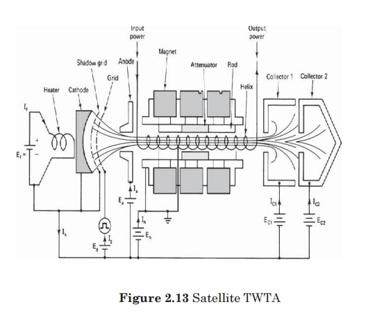
Traveling-wave
tube amplifiers (TWTAs) are widely used in transpon- ders to provide the final
output power required to the transmit antenna. Figure 2.13 shows the schematic
of a traveling wave tube (TWT) and its power supplies.
In
the TWT, an electron-beam gun assembly consisting of a heater, a cathode, and
focusing electrodes is used to form an elec- tron beam. A magnetic field is
required to confine the beam to travel along the inside of a wire helix.
used
in ground stations, the magnetic field can be provided by means of a solenoid
and dc power supply. The comparatively large size and high power consumption of
solenoids make them unsuitable for use aboard satellites, and lower-power TWTs
are used which employ permanent- magnet focusing.
The
wave actually will travel around the helical path at close to the speed of
light, but it is the axial component of wave velocity which interacts with the
electron beam.
This
component is less than the velocity of light approximately in the ratio of
helix pitch to circumference. Because of this effective reduction in phase velocity,
the helix is referred to as a slowwave structure.
The
advantage of the TWT over other types of tube amplifiers is that it can provide
amplification over a very wide bandwidth. Input levels to the TWT must be
carefully controlled, however, to minimize the effects of certain forms of
distortion.
The
worst of these result from the nonlinear transfer characteristic of the TWT,
illustrated in Fig. 2.14.
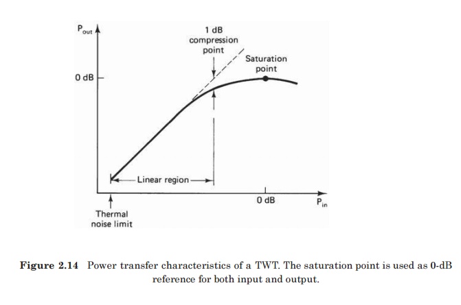
At
low-input powers, the output-input power relationship is linear;
that
is, a given decibel change in input power will produce the same decibel change
in output power. At higher power inputs, the output power sat- urates, the
point of maximum power output being known as the satu- ration point.
The
saturation point is a very convenient reference point, and input and output
quantities are usually referred to it. The linear region of the TWT is defined
as the region bound by the thermal noise limit at the low end and by what is
termed the 1-dB compression point at the upper end. This is the point where the
actual transfer curve drops
Related Topics