Chapter: Satellite Communication : Space Segment and Satellite Link Design
Attitude Control & Orbit Control
Attitude Control
& Orbit Control:
The
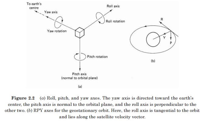
attitude of a satellite refers to its orientation in space. Much of the
equipment carried aboard a satellite is there for the purpose of control- ling
its attitude. Attitude control is necessary, for example, to ensure that
directional antennas point in the proper directions.
In
the case of earth environmental satellites, the earth-sensing instruments must
cover the required regions of the earth, which also requires attitude control.
A number of forces, referred to as disturbance torques, can alter the attitude,
some examples being the gravitational fields of the earth and the moon, solar
radiation, and meteorite impacts.
Attitude
control must not be con- fused with station keeping, which is the term used for
maintaining a satellite in its correct orbital position, although the two are
closely related.
To
exercise attitude control, there must be available some measure of a
satellite’s orientation in space and of any tendency for this to shift. In one
method, infrared sensors, referred to as horizon detectors, are used to detect
the rim of the earth against the background of space.
With
the use of four such sensors, one for each quadrant, the center of the earth
can be readily established as a reference point.
Usually,
the attitude-control process takes place aboard the satellite, but it is also
possible for control signals to be transmitted from earth, based on attitude
data obtained from the satellite.
Also,
where a shift in attitude is desired, an attitude maneuver is executed. The
control signals needed to achieve this maneuver may be transmitted from an
earth station.
Controlling
torques may be generated in a number of ways. Passive attitude control refers
to the use of mechanisms which stabilize the satellite without putting a drain
on the satellite’s energy supplies; at most, infrequent use is made of these
supplies, for example, when thruster jets are impulsed to provide corrective
torque. Examples of passive attitude control are spin stabilization and gravity
gradient sta- bilization.
The
other form of attitude control is active control. With active atti- tude
control, there is no overall stabilizing torque present to resist the
disturbance torques. Instead, corrective torques are applied as required in
response to disturbance torques. Methods used to generate active control
torques include momentum wheels, electromagnetic coils, and mass expulsion
devices, such as gas jets and ion thrusters.
1. Spinning
satellite stabilization:
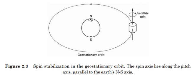
Spin
stabilization may be achieved with cylindrical satellites. The satellite is
constructed so that it is mechanically balanced about one partic- ular axis and
is then set spinning around this axis. For geostationary satellites, the pin
axis is adjusted to be parallel to the N-S axis of the earth, as illustrated in
Fig. 7.5. Spin rate is typically in the range of 50 to 100 rev/min. Spin is
initiated during the launch phase by means of small gas jets.
In
the absence of disturbance torques, the spinning satellite would maintain its
correct attitude relative to the earth. Disturbance torques are generated in a
number of ways, both external and internal to the satellite. Solar radiation,
gravitational gradients, and meteorite impacts are all generated in a number of
ways, both external and internal to the satellite. Solar radiation,
gravitational gradients, and meteorite impacts are all examples of external
forces which can give rise to disturbance torques. Motor- bearing friction and
the movement of satellite elements such as the antennas also can give rise to
disturbance torques. The
overall
effect is that the spin rate will decrease, and the direction of the angular
spin axis will change. Impulse-type thrusters, or jets, can be used to increase
the spin rate again and to shift the axis back to its cor- rect N-S
orientation.
Nutation,
which is a form of wobbling, can occur as a result of the disturbance torques
and/or from misalignment or unbalance of the control jets. This nutation must
be damped out by means of energy absorbers known as nutation dampers.
The
antenna feeds can therefore be connected directly to the transponders without
the need for radiofrequency (rf) rotary joints, while the complete platform is
despun. Of course, control signals and power must be transferred to the despun
section, and a mechanical bearing must be provided.
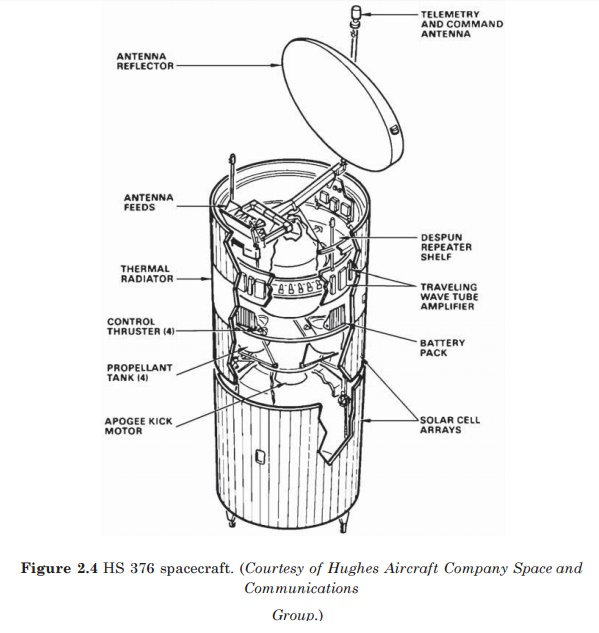
The
complete assembly for this is known as the bearing and power transfer assembly
(BAPTA). Figure 2.4 shows a photograph of the internal structure of the HS 376.
Certain
dual-spin spacecraft obtain spin stabilization from a spinning fly- wheel
rather than by spinning the satellite itself. These flywheels are termed
momentum wheels, and their average momentum is referred to as momentum bias
2. Momentum
wheel stabilization
In
the previous section the gyroscopic effect of a spinning satellite was shown to
provide stability for the satellite attitude.
Stability
also can be achieved by utilizing the gyroscopic effect of a spinning flywheel,
and this approach is used in satellites with cube-like bodies (such as shown in
Fig. and the INTELSAT V type satellites shown in Fig. These are known as
body-stabilized satellites.
The
complete unit, termed a momentum wheel, consists of a flywheel, the bearing
assembly, the casing, and an electric drive motor with associated electronic
con- trol circuitry.
The
flywheel is attached to the rotor, which consists of a permanent magnet
providing the magnetic field for motor action. The stator of the motor is
attached to the body of the satellite.
Thus
the motor provides the coupling between the flywheel and the satellite
structure. Speed and torque control of the motor is exercised through the
currents fed to the stator.
.
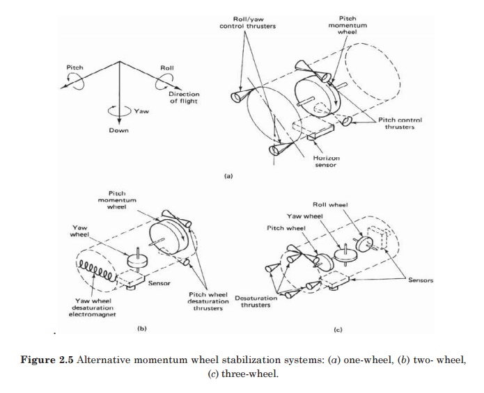
Figure 2.5 Alternative momentum wheel stabilization systems: (a) one-wheel, (b)
two- wheel, (c) three-wheel.
When
a momentum wheel is operated with zero momentum bias, it is generally referred
to as a reaction wheel. Reaction wheels are used in three- axis stabilized
systems. Here, as the name suggests, each axis is stabilized by a reaction
wheel, as shown in Fig. 7.8c. Reaction wheels can also be combined with a
momentum wheel to provide the control needed (Chetty, 1991).
Random
and cyclic disturbance torques tends to produce zero momentum on average.
However, there will always be some disturbance torques that causes a cumulative
increase in wheel momentum, and eventually at some point the wheel saturates.
In effect, it reaches its maximum allowable angular velocity and can no longer take in any more momentum. Mass expulsion devices are then used to unload the wheel, that is, remove momentum from it (in the same way a brake removes energy from a moving vehicle). Of course, operation of the mass expulsion devices consumes part of the satellite’s fuel supply.
Related Topics