Chapter: Satellite Communication : Space Segment and Satellite Link Design
Downlink
Downlink
The
downlink of a satellite circuit is the one in which the satellite is transmitting the signal and the earth station is receiving it. Equation can be
applied to the downlink, but subscript D
will be used to denote specifically that the downlink is being considered. Thus
Eq. becomes

In
Eq. the values to be used are the satellite EIRP, the earth- station receiver
feeder losses, and the earth-station receiver G/T. The free space and other
losses are calculated for the downlink frequency. The resulting
carrier-to-noise density ratio given by Eq. is that which appears at the
detector of the earth station receiver.
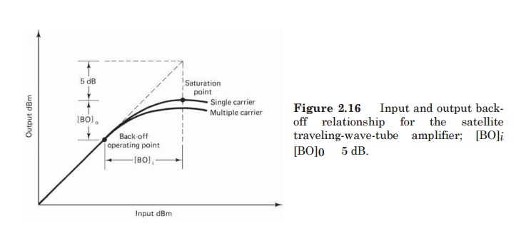
1. Output
back-off
Where
input BO is employed as described in a corresponding output BO must be allowed
for in the satellite EIRP. As the curve of Fig. 2.16 shows, output BO is not
linearly related to input BO. A rule of thumb, frequently used, is to take the
output BO as the point on the curve which is 5 dB below the extrapolated linear
portion, as shown in Fig. 12.7. Since the linear portion gives a 1:1 change in
decibels, the relationship between input and output BO is [BO]0 [BO]i 5 dB. For
example, with an input BO of [BO]i 11 dB, the corresponding output BO is [BO]0
2. Effects of
Rain
In
the C band and, more especially, the Ku band, rainfall is the most significant
cause of signal fading. Rainfall results in attenuation of radio waves by
scattering and by absorption of energy from the wave.
Rain
attenuation increases with increasing frequency and is worse in the Ku band
compared with the C band.
This
produces a depolarization of the wave; in effect, the wave becomes ellipti-
cally polarized. This is true for both linear and circular polar- izations, and
the effect seems to be much worse for circular polarization (Freeman, 1981).
The
C/N0 ratio for the downlink alone, not counting the PNU
contribution, is PR/PND, and the combined C/N0
ratio at the ground receiver is
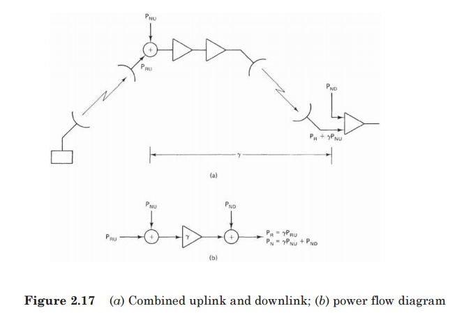
The
reason for this reciprocal of the sum of the reciprocals method is that a
single signal power is being transferred through the system, while the various
noise powers, which are present are additive. Similar reasoning applies to the
carrier-to-noise ratio, C/N.
Related Topics