Physics Practical Experiment - Specific Resistance of the Material of the Coil Using Metre Bridge | 12th Physics : Practical
Chapter: 12th Physics : Practical
Specific Resistance of the Material of the Coil Using Metre Bridge
SPECIFIC RESISTANCE OF THE MATERIAL
OF THE COIL USING METRE BRIDGE
AIM
To
determine the specific resistance of the material of the given coil using metre
bridge.
APPARATUS REQUIRED
Meter
bridge, galvanometer, key, resistance box, connecting wires, Lechlanche cell,
jockey and high resistance.
FORMULA

where,
X
ŌåÆ Resistance of the given coil (Ōä”)
R
ŌåÆ Known resistance (Ōä”)
L
ŌåÆ Length of the coil (m)
r
ŌåÆ Radius of the wire (m)
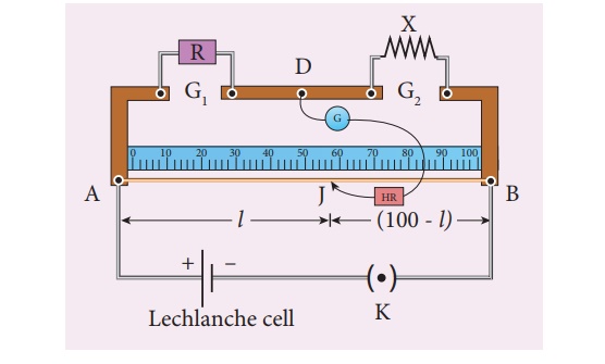
CIRCUIT DIAGRAM

PROCEDURE
┬Ę
A resistance box R is connected in the
left gap and the unknown resistance X in the right gap.
┬Ę
A Lechlanche cell is connected across
the wire of length 1 m through a key.
┬Ę
A sensitive galvanometer G is connected
between the central strip and the jockey through a high resistance (HR).
┬Ę
With a suitable resistance included in
the resistance box, the circuit is switched on.
┬Ę
To check the circuit connections, the
jockey is pressed near one end of the wire, say A.
┬Ę
The galvanometer will show deflection in
one direction. When the jockey is pressed near the other end of the wire B, the
galvanometer will show deflection in the opposite directions. This ensures that
the circuit connections are correct.
┬Ę
By moving the jockey over the wire, the
point on the wire at which the galvanometer shows null deflection i.e.,
balancing point J is found.
┬Ę
The balancing length AJ = l is noted.
┬Ę
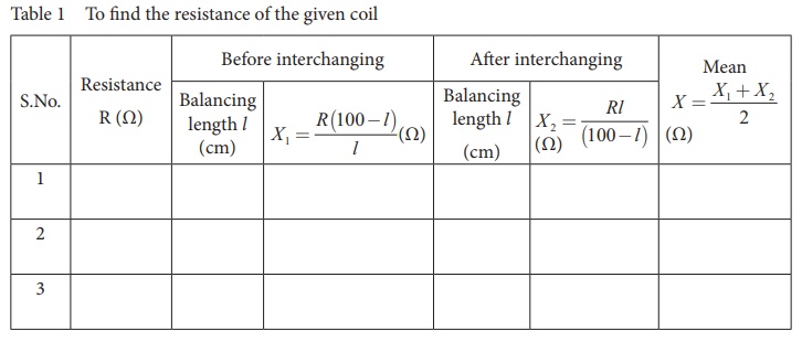
The unknown resistance X1 is
found using the formula X1
= R (100 ŌłÆl) / l
┬Ę
The experiment is repeated for different
values of R.
┬Ę
The same procedure is repeated after
interchanging R and X.
┬Ę
The unknown resistance X2 is
found using the formula X2 = Rl
/ (100 ŌłÆl)
┬Ę
The experiment is repeated for same
values of R as before.
┬Ę
The resistance of the given coil is
found from the mean value of X1 and X2.
┬Ę
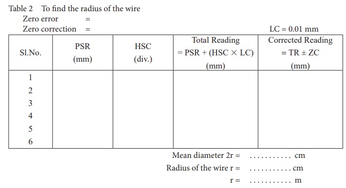
The radius of the wire r is found using
screw gauge.
┬Ę
The length of the coil L is measured
using meter scale.
┬Ę
From the values of X, r and L, the
specific resistance of the material of the wire is determined.
OBSERVATION
length
of the coil L = ____________________________________ cm.
Table
1 To find the resistance of the given coil

Table
2 To find the radius of the wire
Zero
error =
Zero
correction =

CALCULATION
RESULT
The
specific resistance of the material of the given coil =
_____________________(╬®m)
Note:
i.
To check the circuit connections:
The
meter bridge wire is touched near one end (say, end A) with jockey,
galvanometer shows a deflection in any one direction. Now the other end (say,
end B) is touched. If the galvanometer shows a deflection in the opposite
direction, then the circuit connections are correct.
ii.
The usage of high resistance (HR):
The
galvanometer is a very sensitive device. If any high current flows through the
galvanom-eter, its coil gets damaged. Therefore in order to protect the
galvanometer, a high resistance (HR) is used. When HR is connected in series
with the galvanometer, the current through it is reduced so that the
galvanometer is protected. But the balancing length is not accurate.
iii.
To find the accurate balancing length:
The
HR is first included in the circuit (that is, the plug key in HR is removed),
the approx-imate balancing length is found. Now HR is excluded in the circuit
(that is, the plug key in HR is closed), then the accurate balancing length is
found.
Related Topics
