Physics Practical Experiment - Verification of De MorganŌĆÖs Theorems | 12th Physics : Practical
Chapter: 12th Physics : Practical
Verification of De MorganŌĆÖs Theorems
VERIFICATION OF DE MORGANŌĆÖS
THEOREMS
AIM:
To
verify De MorganŌĆÖs first and second theorems.
COMPONENTS REQUIRED:
Power
Supply (0 ŌĆō 5V), IC 7400, 7408, 7432, 7404, and 7402, Digital IC trainer kit,
connecting wires.
FORMULA

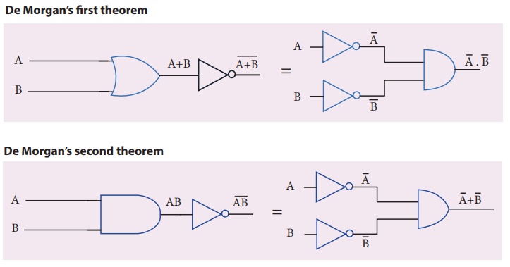
CIRCUIT DIAGRAM:
De MorganŌĆÖs first theorem, De MorganŌĆÖs second theorem

PROCEDURE:
i) Verification of De MorganŌĆÖs first theorem
┬Ę
The connections are made for LHS  of the theorem as shown in the circuit diagram using appropriate ICs.
┬Ę
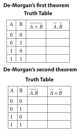
The output is noted and tabulated for
all combinations of logical inputs of the truth table.
┬Ę
The same procedure is repeated for RHS  of the theorem.
┬Ę
From the truth table, it can be shown
that 
ii) Verification of De MorganŌĆÖs second theorem
┬Ę
The connections are made for LHS  of the theorem as shown in the circuit diagram using appropriate ICs.
┬Ę
The output is noted and tabulated for
all combinations of logical inputs of the truth table.
┬Ę
The same procedure is repeated for RHS  of the theorem.
┬Ę
From the truth table, it can be shown
that 
OBSERVATION
De-MorganŌĆÖs first theorem, De-MorganŌĆÖs second theorem

RESULT
De
MorganŌĆÖs first and second theorems are verified.
Note
The
pin diagram for IC 7408, IC 7432 and IC 7404 can be taken from previous
experiment
Precautions
VCC
and ground pins must not be interchanged while making connections. Otherwise
the chip will be damaged.
For
the ICs used, 5V is applied to the pin 14 while the pin 7 is connected to the
ground.
Related Topics