Chapter: Civil : Principles of Solid Mechanics : One Dimensional Plasticity for Design
Plastic Bending
One Dimensional Plasticity for Design
In the previous pages,
a full-range plasticity solution for an EPS thick ring was developed in detail
to illustrate the fundamental concepts of plastic anal-ysis. This was possible
only because a thick ring subjected to internal or exter-nal ŌĆ£pressureŌĆØ is
essentially a one-dimensional problem in that there is only one governing
equilibrium equation since there is no variation of the field in the hoop
direction. At any stage of plastic deformation, this equation can be integrated
directly to determine the stress field. The strain and deformation field is
then determined from the behavior of the elastic rim, which has not yet
yielded.
The same is true for pure bending and
the other one-dimensional linear elastic fields of previous pages. It is also
possible to obtain full plasticity solutions in pure torsion for many cases
considered in previous pages. Combinations of lin-ear fields can also be
considered. Since limit analysis and design* of beams, shafts, frames, plates,
and many other structural systems are based on these one-dimensional plasticity
solutions, it is important to study them.
Plastic Bending
The basic assumption of the theory of
flexure as stated in Section 5.5 is that plane sections normal to the axis of
the beam remain plane so that the beam under pure bending deforms into a circle
with radius of curvature Žü. This assumption as to
the geometry of deformations has nothing to do with mate-rial properties and
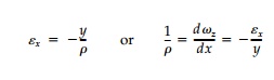
requires that longitudinal strains, Ex,
in the fibers vary directly as their distance, y, from the neutral axis
as given by Equation (5.15).
Thus, from equilibrium
requirements, a general theory can be developed for bending beyond initial
yield.*
Any prismatic beam with a cross-section
with symmetry about a vertical axis can be considered. The neutral axis,
defined as where the strain is zero, goes through the centroid in the elastic
range but may migrate as the yield-ing progresses such that horizontal
equilibrium is maintained. That is C = T or
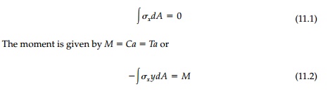
The solution of the
general case of inelastic bending requires that these equi-librium Equations
(11.1) and (11.2) for the given stressŌĆ'strain relationship be solved by trial
and error. Two relatively simple cases are explored as chapter problems.
Let us consider only the case of a beam of an elastic, perfectly-plastic solid and start with a rectangular cross-section as shown in Figure 11.1. At yield of the outermost fibers, the moment MY = YI/c = Ybh2/6 = YS. As more moment is applied, the plastic zone moves toward the neutral axis and, because of our idealization of the material as an EPS, there is a sharp separa-tion leaving an elastic core at the center. If, for example, the strain at the outer surface is twice the yield strain,ŽĢ =2ŽĢY, the middle half of the beam remains elastic (Figure 11.1b) and the moment works out to be 11/48 Ybh2. At very large rotations of the cross-section, as in Figure 11.1c, the linear distribution in the small elastic core can be neglected and the stress assumed as Y throughout. Thus, this ultimate or plastic moment is
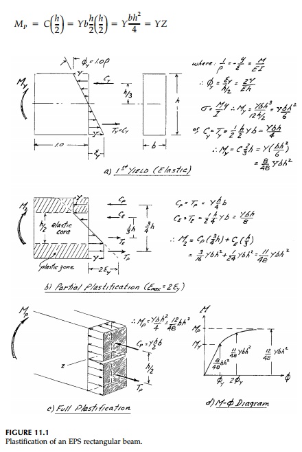
Throughout, the neutral
axis remains at mid-height because of the sym-metry around the z axis
coupled with the requirement that the compres-sion force in the top equal the
tension force in the bottom. The elastic section modulus, S, and plastic
section modulus, Z, are given in various handbooks for standard shapes
such as angles, channels, wideflange, and I beams. The ratio Z/S = MP/My is often called the shape factor, Ks.
For a rectangular cross-section then, Ks=1.5 indicating this shape has a large reserve capacity to take additional
moment beyond yield because of its inefficiency in the elastic range. For WF
and I beams, Ks = 1.12 and it takes
only 12% more moment to fully plasticize the section as to yield it.
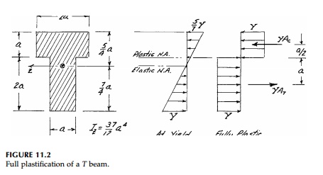
As a second example, consider the T beam in
Figure 11.2. The moment of inertia about the centroidal axis Iz = (37/12) a4 and therefore the elastic yield
moment:
As the moment increases beyond that necessary to
yield the outermost fiber at the bottom, the neutral axis must shift upward
since horizontal equilibrium requires that the compression in the top always
equal the tension in the bottom. Finally, at full plastification, when all the
fibers reach yield, C= YAc = T = YAt and the fully plastic neutral
axis is at the junction of the flange and web since, there, Ac=At = 2a2. Thus
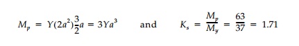
This shape factor is
roughly the same for any T beam showing they are even less efficient
than rectangular cross-sections in the elastic range.
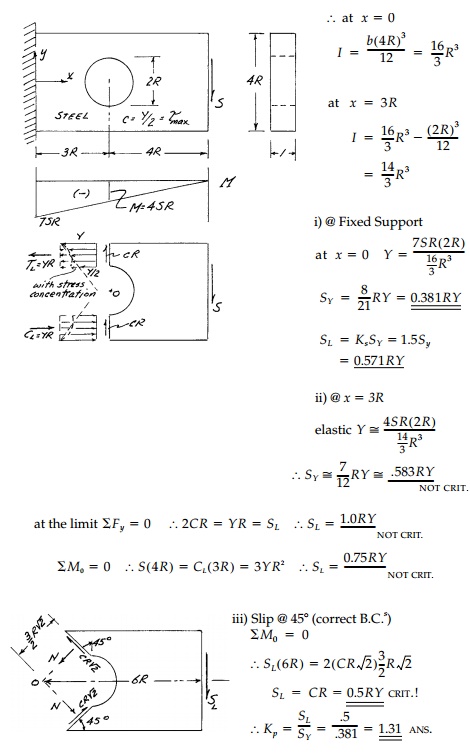
Example 11.1
A steel cantilever beam with a hole in it is loaded
with a vertical shear force (distributed parabolically) at its free end as
shown. From simple beam theory (plane sections) determine the yield load SY
. Estimate the limit load from an upper-bound approach and thereby the
plasticity factor SL/SY .
Related Topics