Chapter: Civil : Principles of Solid Mechanics : One Dimensional Plasticity for Design
Limit Analysis of Frames and Arches
Limit Analysis of Frames and Arches
The upper-bound analysis of frames and arches
follows much the same strategy as for beams. However, in addition to the
location of enough plastic hinges to bring about collapse, there may be a
variety of ways they can be arranged into different “failure mechanisms” and,
of course, the interaction effect of axial forces may reduce the moment
capacity in a nonlinear way (Figure 11.4) as the loads increase. We will
consider a few simple examples to illustrate these concepts.
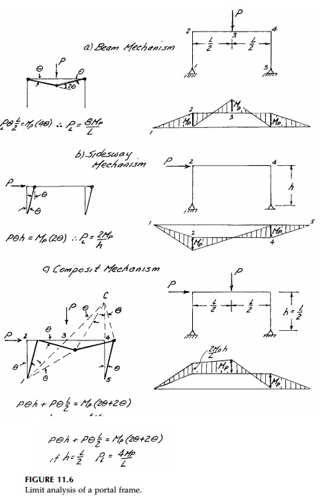
Consider first a basic single-story portal frame
(Figure 11.6). For a concen-trated load at midspan, a local beam mechanism
would occur at PL = 8MP/L.
Similarly, if the wind loading is approximated by a concentrated lateral force P
at the top, the local “panel” or sidesway mechanism would occur at PL = 2MP/h. If, for example, h =L/2
then PL = 4MP/L
and the panel mechanism would occur first. Finally, with both loads acting, a
composite mechanism is possible. For the
particular case where h = L/2, this mode
of collapse occurs simultaneously with the panel mechanism at PL = 4MP/L.
Also shown in Figure 11.6 is the instantaneous center approach to the virtual
work calculation. There are three movable parts that rotate as rigid bodies.
Part 123 rotates about 1, part 45 rotates about 5 and part 34 must therefore
rotate about a point C, located as shown (since point 3 rotates about
both A and C, point 4 rotates about both 5 and C). The
instantaneous-center method is particularly useful for gable frames and arches.
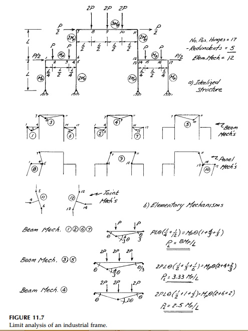
Multistory and/or multibay frames are more involved
but conceptually no more difficult. An example is presented for a 5-degree
indeterminate frame in Figure 11.7. The simplicity of the limit analysis
compared to an elastic analysis is dramatic. For an actual design, the moment
capacities of the members, par-ticularly the inner columns, would need to allow
for the axial-load interaction effects. As might be expected, the critical
mechanism has six plastic hinges. As each one forms, the structure becomes one
degree less indeterminate until, with the sixth, it becomes unstable giving the
extra equilibrium equation needed to solve for the critical load.
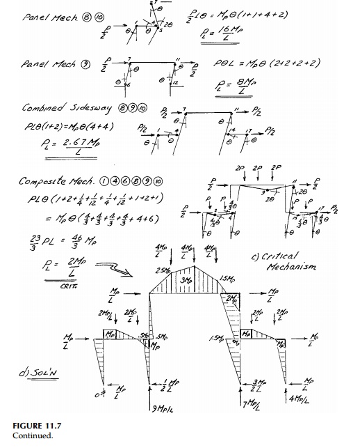
The minimization strategy becomes clear as you work
with various trial mechanisms. Obviously, you want to reduce the number of
hinges and the angles through which they rotate to keep the internal plastic
energy low while at the same time getting all the loads to move to increase the
external work. Moreover, from a design perspective it quickly becomes apparent
where increasing moment capacity can help and where it will not. Since the
calculations are so simple so is a design by successive approximation. Usu-ally
for structures, determining the collapse load for each possible mecha-nism by
equilibrium equations is much more difficult than by using a work calculation.
However, when you have found what you think is the upper-bound minimum, in this
case PL = 2MP/L,
you must use the equilibrium equations to solve for the reactions and plot the
moment diagram (Figure 11.7d) to make sure that at no point is M> MP and thereby check that you have, in fact, determined the
correct solution.
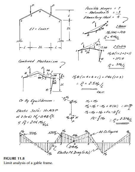
Two further examples of simple limit analysis, a
gable frame and a circular arch each with constant cross-section, are shown in
Figures 11.8 and 11.9. In both cases the analysis is made easier by assuming
concentrated loads. The elastic bending solution is shown for the gable frame
to compare to the col-lapse bending moment diagram. The redistribution factor
is simply the ratio of the areas of the two.
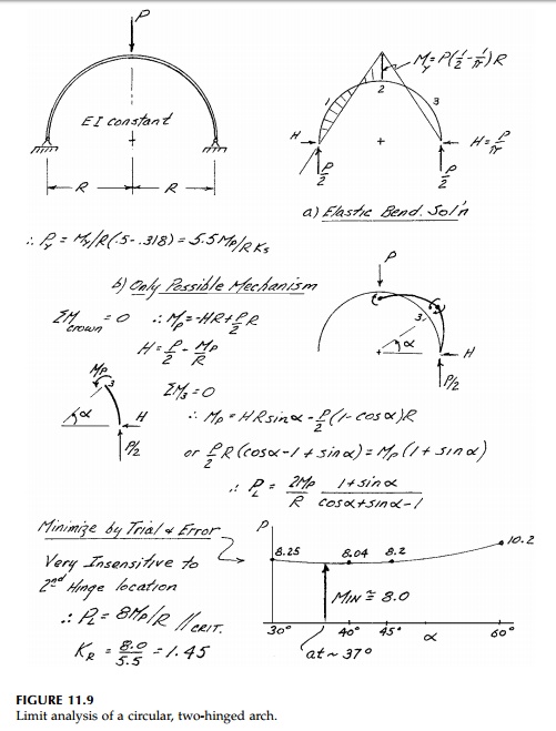
Even with a concentrated load, one possible hinge
location is uncertain for the arch and therefore must be determined by
application of the upper-bound theorem. A formal equation could be derived, but
minimization by trial and error is perfectly adequate. The analysis at these
two structures with uniform loads are called for in the chapter problems where
determining the critical hinge locations is more difficult. For more
complicated structural geometry or loading, graphical analysis for the
kinematics of collapse is perfectly adequate and is commonly used in practice.
Since real arches are designed to transmit loads primarily by axial force, the
bending solution for the collapse load may need to be reduced to include the
interaction effect dis-cussed in Section 11.2.
Related Topics