Chapter: Civil : Principles of Solid Mechanics : One Dimensional Plasticity for Design
Limit Load (Collapse) of Beams
Limit Load (Collapse) of Beams
With the concept of a
plastic hinge it is possible to determine the collapse or limit load of
structures by the upper-bound theorem (as was done for thick rings and the
bearing capacity problem in previews pages). Any type of structure: beams,
frames, arches, plates, even shells, are susceptible to this approach no matter
how complicated or irregular the geometry. Various collapse “mechanisms” are
assumed and the limit or collapse load computed for each from equilibrium or
conservation of energy. That mechanism corresponding to the lowest load is
critical. For linear structures (one-dimensional from the standpoint of
equilib-rium) this minimization procedure by analytic analysis or by trial and
error leads to an “exact” upper-bound solution since only the number and
longitudi-nal position of the discrete plastic hinges are unknown for a limited
number of possible types of collapse mechanisms. For plates and shells, the
exact mecha-nism is much more difficult to determine, but it is often not
really necessary for a good approximation since the type of mechanism is seldom
in doubt.
Only a few examples will be given in this and the
following section to illus-trate the fundamental idea and to show how similar
it is to the yield surface concept used for upper-bound analysis for
two-dimensional stress fields in the previous chapter.* Take first the simple
case of a once-indeterminate
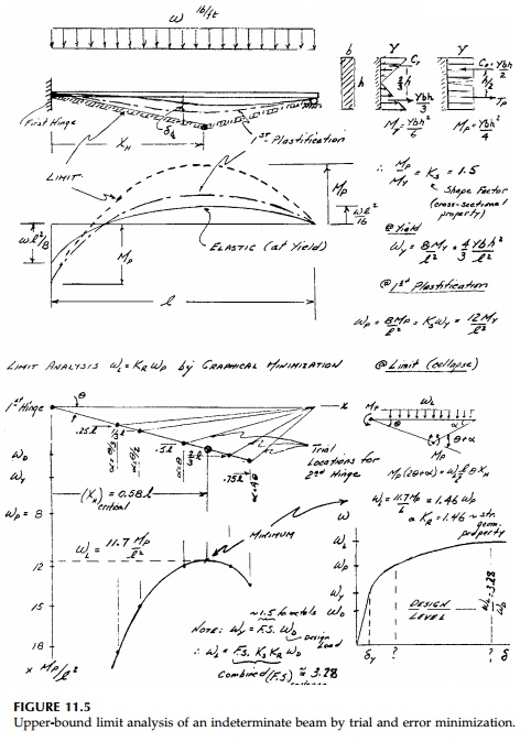
beam with a uniform load shown in Figure 11.5. Two plastic hinges, one at the wall and one near midspan, is the only possible collapse mechanism. The second hinge will be, by the upper-bound theorem, located such that the limit load wL is a minimum. The minimization procedure can be done graph-ically by trial and error as shown or formally. Since (L - x)α=xθthe internal energy dissipation from the rotation of the plastic hinges equated to external work done by wL gives:
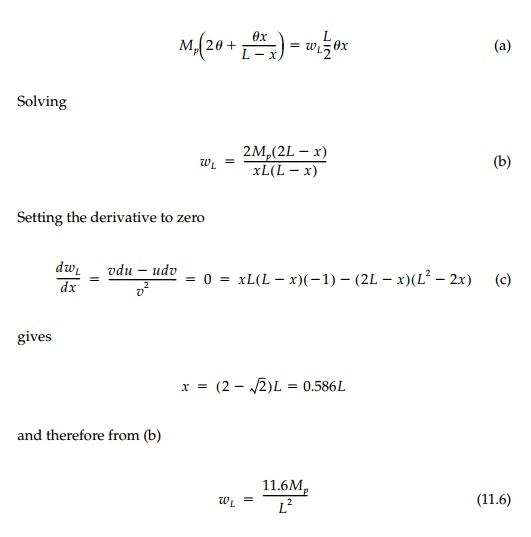
The calculation of the
limit load is seen to be independent of the elastic analysis. The individual
pieces of the structure move as rigid bodies after the plastic hinges form and
the plastic energy, concentrated at the hinges, can be made arbitrarily large
for an EPS material. Thus the elastic contribution can be neglected.
With the formation of the first plastic hinge, the
one-degree indeterminate beam becomes determinate and when the second one
forms, the structure is unstable (on the verge of becoming dynamic). This gives
the extra equation to calculate the limit load. Since the most complicated
indeterminate struc-ture is reduced to a simple computation in statics, limit
analysis is very pop-ular. Moreover, small support settlements or rotations
will not affect the limit load while they have a great influence on the elastic
forces and moments in indeterminate structures.
The price paid for this simplification is the loss
of any straightforward cal-culation of displacements beyond first yield.* As
outlined in Figure 11.5, two interacting nonlinear effects are occurring. The
plastification of the first hinge redistributes the moment diagram which, in
turn, influences the location of the next plastic hinge. The increase in
moment, and therefore load to cause the first plastic hinge is the shape
factor, Ks, which, as we have seen, is a geo-metric property
of the shape of the cross-section. The added strength intro-duced by the
indeterminacy and geometry of the structure can be called the redistribution
factor, KR, defined as
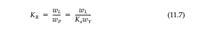
For the beam in Figure 11.5, KR = 1.46 and Ks for a rectangular cross-section is 1.5 giving a
combined plasticity factor KP = Ks KR= wL/wY
=
2.19. Thus, if the beam were designed to give a factor of safety of 1.5
against yield, it would have a factor of safety against collapse of (1.5)(2.19)
=
3.28. Even in an H-beam with Ks = 1.12 and a working load of two-thirds, the yield load would have a factor of
safety against collapse of 2.46 if supported as in Figure 11.5. Such large
reserves against flexural failure are one reason indeterminate bridges and
other structures built in the first half of this century using the
working-stress design code are still functioning well, even though trucks and
trains are now so much heavier.
Related Topics