Chapter: Civil : Principles of Solid Mechanics : One Dimensional Plasticity for Design
Limit Analysis of Plates
Limit Analysis of Plates
The elastic analysis of plates with a distributed
lateral load ŌĆ£q,ŌĆØ while straightforward in concept, can be extremely
complicated because of difficul-ties introduced by the boundary conditions. The
fundamental governing equation in terms of the lateral deflection, w,
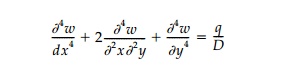
is essentially a ŌĆ£two-wayŌĆØ beam equation where the
flexural rigidity of the plate
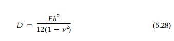
replaces the simple beam rigidity EI. As with
a beam, slopes are proportional to the first derivatives, moments to the second
derivatives, and shears to the third derivatives of the deflection. Thus the
boundary conditions of a free edge, simply-supported edge, and fixed edge can
be expressed. In theory, the elastic problem can be solved directly for
circular plates, by using Fourier series for rectangular shapes, and by
numerical methods for irregular boundaries. Elastic solutions in the form of
extensive tables of coefficients are given in the literature for rectangular
and circular plates.*
In contrast, the limit analysis of plates using the
upper-bound theorem, is straightforward and much easier than elastic analysis.
Simply assume a col-lapse mechanism and calculate the corresponding collapse
load by the energy balance or by equilibrium. While an elastic analysis may
require hours of intensive calculation, a good estimate of the limit load can
be determined in a few minutes. Equally important, a good physical feel for the
structural behav-ior of the plate is obtained in the process.
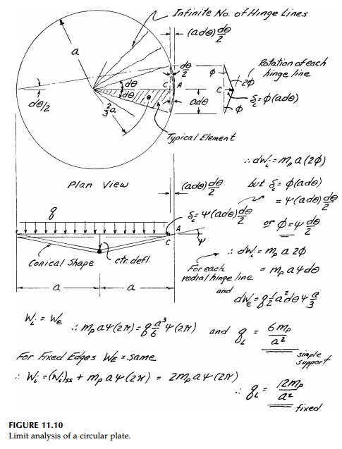
Take, for example, the simple case shown in Figure
11.10 of a circular plate of radius, a, and thickness, h, with a
uniform vertical load, q, over the entire surface. If the edge is simply
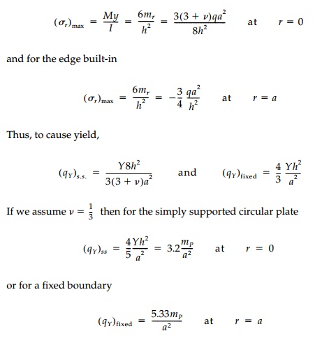
supported (free to rotate) the maximum elastic moment at the center is mr = mt = (3+v)qa2/16.
If the edge is built-in (clamped), the moment at the center is reduced to (1+v)qa2/16
while at the edge the radial moment is mr = - qa2/8
and there is a tangential or twisting moment mt = - v qa2/8.
The corresponding maximum stresses are, for a sim-ply supported plate:
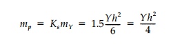
The plastic analysis follows the procedure developed
for linear structures, except that instead of elastic hinge points with a
moment capacity Mp = Ks
My , ŌĆ£hingeŌĆØ lines develop with a moment capacity per unit length.
Because of the
symmetry, the only possible failure mechanism is that, at col-lapse, the
surface is pushed downward into a cone as shown in Figure 11.10. The radial
hinge lines, along which mt =
mp, rotate 2ŽĢ doing internal work
while q over the area of a typical differential slice does external work
moving downward 4a/3. For simply supported edges, the energy balance
gives qL = 6mP/a2
and a reserve strength from first yield to collapse of KP = KsKR = 6/3.2 = 1.875. For the case where the edge is fixed, the edge itself of length 2ŽĆa
becomes a negative hinge line adding ŌłåWi = 2ŽĆampŽł to the total internal work. Thus qL = 12mP/a2 and the reserve strength qL/qY
=
KP = 12/5.33 =
2.25. Thus, not only do plates take greater loads in the elastic range by beam
action in two directions rather than one, but they have greater plastic
load-carrying capacity than beams for the same reason.
Yield-line limit analysis of plates is the flexural
counterpart to yield line or slip-surface analysis for two-dimensional planar
structures. Like the punch problem, the determination of the critical yield
line can be accomplished by trial and error or by a formal minimization
procedure for a particular type of failure mechanism. Only in special cases
like circular plates, is the determination of the exact pattern of yield
surfaces straightforward. In general, how-ever, for plates of uniform
thickness:
i. Hinge lines are straight with a constant mP = Yh2/4,
ii. Axes
of rotation are along supports,
iii. Axes
of rotation are over columns , and
iv. Hinge
lines pass through axes of rotation of adjacent slab segments.
These rules of thumb,
which help guess the critical hinge line patterns, are illustrated with a few
examples in Figure 11.11.
As an example of refining the pattern of hinge lines
to converge by the upper-bound theorem on the critical limit load, consider a
square plate with either pinned or fixed supports shown in Figure 11.12. The
elastic solution gives:
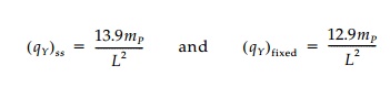
The simplest assumption
for the failure mechanism is diagonal hinges from the corners shown as pattern
#1. The corresponding collapse loads for the simply supported and fixed
boundary cases are calculated by equilibrium to illustrate that this approach
can be used rather than enforcing the energy balance.
However, the corners of a rectangular plate actually
would like to lift off the edge support if not restrained. Thus the moments are
negative near the corners, which act as cantilevers. To capture this, a second
hinge line pattern (#2 in Figure 11.12) with ŌĆ£corner cantileversŌĆØ or ŌĆ£corner
leversŌĆØ should be investigated. For a particular case we see, for the simply
supported plate, that by including the diagonal negative hinge at corners, the qL
is reduced by about 2.5%. Minimi-zation by successive trial and error can
reduce this further to roughly
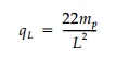
or 9% less than for the simple Pattern #1.
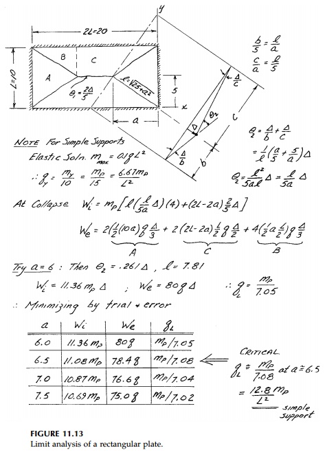
As a final example, consider a 2:1 rectangular plate
shown in Figure 11.11. Assuming the simple mechanism without including the
corner cantilevers, the limit load works out to be qL = mP/7.08 = .1412mP
. Including the corner cantilevers might reduce this 10% to qL
=
.127mP. From the elastic solution
We could now consider what happens if the edges are
fixed or if one edge were free, but these and other examples for rectangular
plates are left as chap-ter problems.
Related Topics