Chapter: Civil : Principles of Solid Mechanics : One Dimensional Plasticity for Design
Plastic ÔÇťHingesÔÇŁ
Plastic ÔÇťHingesÔÇŁ
Once the cross-section
is fully plasticized, it can rotate with no additional moment applied. Thus for
a beam subjected to pure moment (with a constant moment diagram), the entire
beam plasticizes simultaneously and there is unrestrained plastic flow. In the
normal situation where the moment diagram varies, this is not the case.
Consider for example the EPS cantilever beams of
rectangular cross-section with a concentrated load, P, at its free end
shown in Figure 11.3a. Assume that the cross-section at the wall is on the
verge of full plastification
the stress distribution will be as shown in
Figure 11.3d where the elastic zone extends ye from the
neutral axis. Therefore
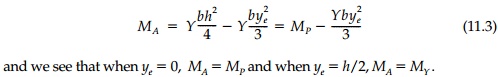
. Since MA is a known function of x
or x* for a given loading, the elastic-plastic interface can be
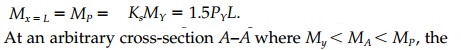
determined from Equation (11.3). In this case,
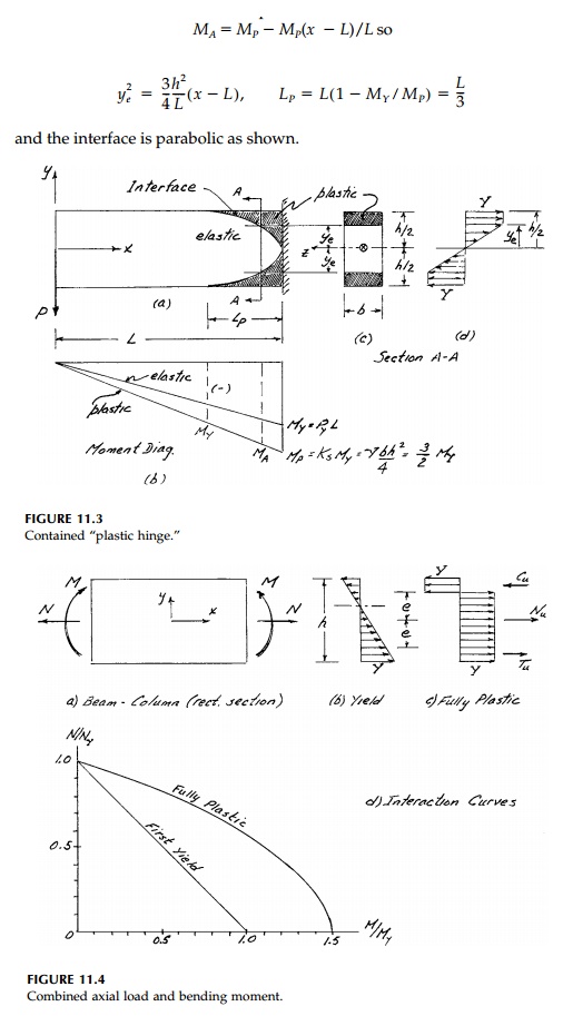
As long as the elastic core remains, plastic flow is constrained. However, when P increases such that PL = MP , the cross-section becomes fully plastic and the curvature can increase without limit but contained within the plas-tic zone. The beam rotates like a rigid body about a ÔÇťplastic hingeÔÇŁ holding the ultimate plastic moment MP . If, as in this case, the structure is determi-nate, it collapses and PL = MP/L = KsMY/L. It should be noted that no pro-vision is made in this simple strength-of-materials approach for the effect of any shear stresses, ¤äxy , or vertical stress, ¤ây , which may be of some signifi-cance in short beams. The chapter problems explore these questions in a preliminary way.
On the other hand, the effect of axial load N
combined with bending moment M in the plastic range is straightforward.
Suppose N and M combine to give the stress state at yield
shown in Figure 11.4b. The maximum stress in the bottom fiber is
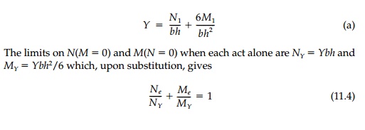
as the elastic
interaction curve for yield shown in Figure 11.4d. When N1 is
zero, M1 = MY and similarly when M1 = 0, N1 = NY. Between these extremes there are
any number of combinations of moment and normal force to cause yield.
If we call Nu and Mu
the combination of normal force and moment to fully plasticize the
cross-section, it is clear from Figure 11.4c that
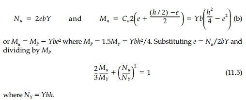
This interaction
relationship plotted in Figure 11.4d gives all combinations of N and M
for full plastification.
Related Topics