Chapter: Civil : Principles of Solid Mechanics : One Dimensional Plasticity for Design
Combined Torsion with Tension and/or Bending
Combined Torsion with Tension and/or Bending
Interaction diagrams for a safe estimate of the effect of combined loadings of prismatic members can be determined from our lower-bound approach to plastic bending and torsion. Consider first the case of torsion and axial force acting simultaneously on a cross-section. Reviewing our yield condition for combined tension and shear shown in Figure 11.19b, for the Tresca criterion:
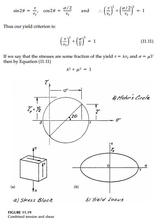
But the stresses are proportional to the torsion and the axial force. That is, with some combined loading, λτY is in equilibrium with λ(Mt)P and μY is in equilibrium with μNY so that
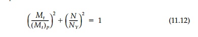
represents the safe combinations. This plots as an ellipse as shown in Figure 11.20a. It is easy to show with the same arguments, that if Mp = Ks My is the fully
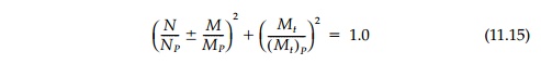
plastic bending moment, then:

represents safe combinations of torque and bending (Figure 11.20b). However, as discussed in Section 11.2, such a simple interaction equation
does not represent safe combinations of bending moment and axial force. This is because both produce normal stresses that combine in a different way
to progressively yield the cross-section. A safe assumption is a straight line connecting
This would be nearly true for an I beam but, as shown in Figure 11.4 and replotted in Figure 11.20c, the safe region can be extended considerably for a rectangular beam.
Nevertheless, using the safe lower-bound straight line relationship [Equation (11.14)], an excellent general safe load locus is:
The positive octant of these two intersecting surfaces is shown in Figure 11.20d derived from the three, two-dimensional loci a, b, and c.
It should be noted that in this discussion of combined loading we have lim-ited ourselves to so-called “compact” cross-sections where buckling instability leading to premature collapse is not a concern. Nor have we considered other than the perfect EPS material. Within those limitations however, we have been able to define safe combinations of torque, axial force, and bending moment independent of the dimensions other than that (Mt)P , NY, and MP depend on the shape of the cross-section. A review of detailed solutions for specific geometries will show that elliptical loci developed for torque with axial force or bending are close to the “correct” interaction curves and therefore efforts to expand the safe zone defined by these relatively simple lower-bound solutions is not warranted for practical design.
Related Topics