Chapter: Civil : Principles of Solid Mechanics : One Dimensional Plasticity for Design
Plastic Torsion
Plastic Torsion
The elastic solution for pure torsion (Previews pages) predicts that the maximum shear stress, τzt, is always a maximum on the boundary and is equal to the slope of the pressurized elastic membrane (or ϕ hill) used in Prandtl’s Mem-brane Analogy presented in previews Sections . Using the Prandtl stress function, the shear stresses are
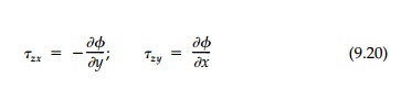
and the equilibrium Equation (9.10) is automatically
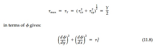
solved. Now, following the strategy of plasticity, we use the yield condition
rather than the compati-bility equation. Writing the Tresca Criterion
Since our boundary condition, ϕ=0, was also based only on equilibrium, it remains applicable in the plastic range. Therefore, the theory of plastic torsion, formulated in terms of Prandtl’s stress function with no reference to strains or displacements, is complete.
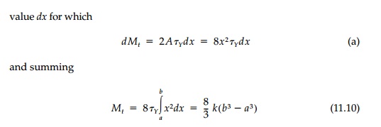
Equation (11.8) tells
us that the square of the gradient of Ď•,
which is the square of the maximum slope of the “ϕ hill” at any point, is equal to the square of the yield stress.
Therefore the “ϕ Hill” in regions of
the cross-section that have gone plastic have a constant maximum slope equal to Ď„Y
.
Sand-Hill and Roof
Analogies
The solution, that in plastic zones the “ϕ Hill” has a constant maximum slope, suggested to Nadai* in 1923 the so-called sand-heap analogy for full plastification. A slope of dry sand has a natural angle of repose slightly greater than the friction angle which, if exceeded, will cause the particles to roll down the hill. Thus if we take a flat horizontal plate of the same shape as the cross-section under torsion and pour sand on it until it will take no more, the resulting surface satisfies the conditions on the plastic “ϕ Hill” that its maximum slope be constant everywhere and its height be zero at the external boundary. Moreover, the expression for the total torque
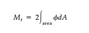
remains valid since it
again is based only on equilibrium. Thus the torque applied to the
cross-section is twice the volume of sand on the plate (easily determined in
the laboratory by weighing it).
We can also think of
the sand-hill analogy as a roof of straight sections of constant slope, Ď„Y,
in the shape of the sand-hill surface erected over the cross-section. This
allows us to better visualize stages of partial plastification by thinking of
the pressurized membrane inside representing the elastic “ϕ Hill” being pressed flat against the limiting roof in the plastic zones and
still curv-ing beneath the roof where the cross-section remains elastic. This
is illus-trated in Figure 11.14a for a circular and a square cross-section. At
initial yield the membrane first touches the roof at some point or points at
the boundary. With further increase in air pressure, which is directly
proportional to the rate of twist and therefore the torque, the membrane
gradually touches more and more of the roof until, at full plastification,
there is no space between them.
These analogies give us both a heuristic way to
visualize solutions and, for fairly simple shapes, a device to actually
calculate exact values for the fully plastic torque (Mt)P
. Since Ď„Y
flows along contour lines, it abruptly changes direction at “ridge lines”
which, since the slope is constant, must bisect corner angles. Also, since the
slope is constant, the contours are equidistant.
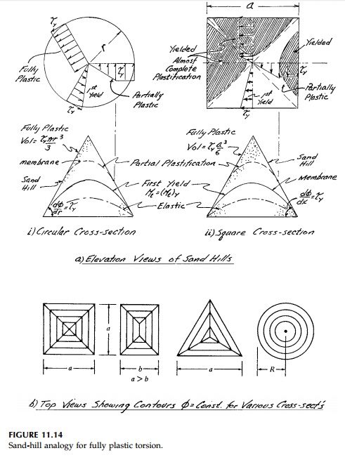
For example, contour lines for some simple shapes
are shown in Figure 11.14b. The sand hill for a circular cross-section is a
cone of height Ď„YR/2.
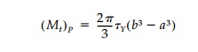
Thus the ulti-mate torque capacity is:
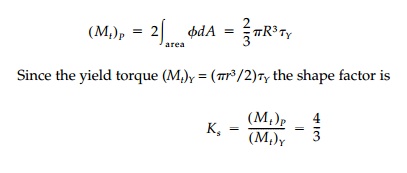
This result for a
circular cross-section is, of course, just as easily found by direct
integration as is done in the introductory course in strength of materi-als.
Calculating the plastic torque and shape factors for a variety of other solid
cross-sections including those in Table 9.1 are included as chapter problems.
This lower-bound plasticity solution is so straightforward for simple shapes
because the sand-hill analogy is so powerful.
Sections with Holes
and Keyways
The sand-hill analogy can be applied to sections with holes and keyways, although using it for computation of the plastic torque becomes much more dif-ficult. Consider for example, Figure 11.15b showing a circular hole eccentrically placed in a circular cross-section. We need to visualize that a thin-walled vertical tube is inserted in the hole in the circular plate before the sand is poured on the plate. We then lower the tube allowing the sand to fall down it until its surface area is covered. In Figure 11.15b the top of the tube would be τYh above the plate. Therefore the boundary conditions, θ=0 at the edge of the plate and θ= τYh (constant) on the edge of the hole, are satisfied. Twice the volume of the sand hill is the plastic torque, but it will not be easy to compute.*
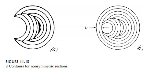
In cases without symmetry such as shown in Figure
11.15, it is easier to draw the contours and compute the plastic torque using
the “onion” analogy or “nesting tube” lower-bound approximation presented by
Calladine.
We have seen in Section 9.5 (Figure 9.12) from
equilibrium considerations only that for thin-walled tubes of arbitrary shape

where A is not the area of the cross-section
but the area enclosed by the aver-age perimeter. If we make t a
constant, then at yield
Thus we can obtain a
lower-bound solution for the plastic torque by dividing the cross-section into
a set of nesting thin-walled tubes where each tube has the same constant
thickness and encloses the largest possible area.
The procedure is,
starting at the outer edge, to cut or strip off complete thin tubes each of the
same constant thickness (so Ď„ = Ď„Y)
until the cross-section is used up. We then sum the torques from each nested
tube from Equation (11.9) to give the total plastic torque, which will be a
lower bound. Calladine* uses the term “onion” analogy and it is clear that, in
the limit, it is the same as the sand-hill analogy. However, it is much clearer
conceptu-ally, particularly for complicated shapes, and much easier to draw and
compute.
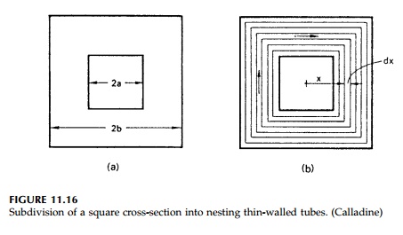
Take, for example, the hollow square tube in Figure
11.16. This strategy of graphical analysis gives a set of nested square tubes.
Because of the regular geometry we can reduce the thickness of each tube, 2x
on a side, to a differential
This lower-bound approach gives the exact value in
this case where calculus can be used.

For cross-sections with holes, the calculation is
more difficult but manage-able, and the conceptual visualization is clear. Take
for example the circular cross-section with a triangular hole shown in Figure
11.17. Starting from the outside we get four complete nested tubes, but then we
are left with three irreg-ular zones. Our striping procedure must produce
complete tubes so we con-tinue on as shown. With a ruler, protractor, and some
poetic license we can determine the area circumscribed by each of the three
onion slices in each of these three areas and their contribution to the total
plastic torque. They turn out to be small and neglecting them and using only
the four circular tubes gives a satisfactory lower-bound value
It is clear that this “stripping” procedure is
perfectly general and that by using it we can develop a satisfactory lower-bound
estimate for the plastic torque for any cross-section, no matter how irregular.
Starting from the outside, rings of uniform cross-section are “removed”
treating separately any areas that may become separated in the process. Areas
can be evaluated by graphical approximations with or without the aid of a
planimeter. Figure 11.18 shows
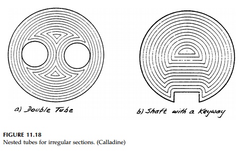
two more examples that emphasize the relative
simplicity of the nested-tube approach compared to the sand-hill analogy in
visualizing the contours of the “ϕ hill” for complicated
sections.
Related Topics