Chapter: Civil : Principles of Solid Mechanics : Concepts of Plasticity
The Bearing Capacity (Indentation) Problem
Example - the Bearing Capacity
(Indentation) Problem
The contact problem of
a foundation, bearing plate, or punch being driven into a body is encountered
throughout engineering practice. As an introduc-tion we will consider here only
the simplest idealization by assuming:
1. The
material being indented (the foundation) is an EPS material.
2. Plane
strain (a long indenter) so that the out-of-plane stress is every-where the
intermediate principal stress.
3. The
actual distribution of contact pressure is not important and can therefore be
considered uniform.
4. There
are no contact shears (a smooth indenter).
5. The
weight of the foundation material can be neglected.
6. The Tresca yield condition; i.e. 
In succeeding pages a
more thorough analysis for this general problem will be given and an “exact”
solution obtained for this simple case using slip-line theory. However, it is
extremely important to appreciate the simplicity and power of the trial-and-error
approach using the upper-bound theorem before it is masked by the complexity of
this theory.* For most bearing capacity prob-lems and, for that matter, most
two-dimensional problems in general, the assumptions above are only approximate
at best and boundary conditions (geometry and loading) are complex. Thus the
engineer usually faces problems for which “exact” answers are extremely
difficult or impossible to obtain. Good approximate analysis using the
upper-bound approach is, however, generally simple and always possible.
Moreover, it develops that physical feel and sensi-tivity as to which variables
are most significant, which is so essential for good design. Thus the
upper-bound concept and its application will be emphasized in this section and
hereafter.
Circular Mechanisms
The first and most
crucial step in upper-bound analysis is to postulate a geo-metrically possible
failure mode or “mechanism” of collapse. The closer this is to the “correct”
mechanism, the closer one approaches the “correct” answer, but there are trade-offs
involved in that the subsequent calculation of the load to cause collapse must
be reasonably easy. In fact, since after the mechanism is selected the problem
of evaluating the corresponding failure load is simply a statics problem,*
choosing and drawing a collapse mechanism is analogous to selecting the most
advantageous free-body diagram to draw in structural analy-sis. Ninety-nine
percent of thought and judgment should be spent on this first step since the
remaining work is straightforward mechanical application of force equilibrium
or its energy counterpart.
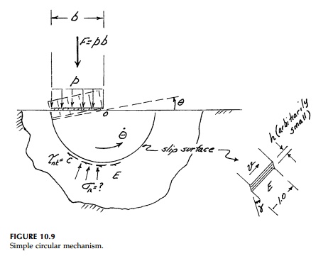
Perhaps the simplest
possible mechanism is rotation about one corner as shown in Figure 10.9. The
bearing, plate (indenter) rotates as a rigid body with angular velocity .
around a corner and there is an intense shear zone (a slip surface) outside of
which (region E) the EPS foundation material remains elastic. In this
zone, which can be made arbitrarily narrow since the plastic plateau is assumed
infinite, the shear stress must be
where v velocity
of plastic deformation of one surface relative to the other. Therefore,
equating external to internal work (in a small time)
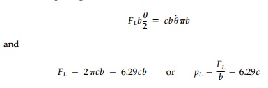
It is important to note
that for this circular mechanism, the calculation could just as easily
be done using equilibrium by taking moments about the corner at 0:
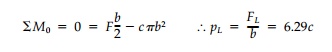
However, this is only
possible since the unknown normal stresses on the cir-cular slip surface have
no moment arm.
Thus we have found,
very simply, an upper-bound estimate for the collapse load and it must
be higher than the actual collapse load. The search for pos-sible lower values
for circular mechanisms in general can now be pursued by changing the origin
and radius. This can be done as in the previous example, either by trial and
error using a graphical minimization procedure, or for-mally (see P10.17).
However, unlike the example of a loaded beam where the fundamental type of
mechanism is known (i.e., plastic hinges), optimization of the location of the
circular slip surface to reduce pL to a minimum will not
converge to the exact solution since this type of mechanism (circular) is not
the correct shape to start off with (see P10.19).
Sliding Block
Mechanisms
Another geometrically
possible class of failure modes for this problem is made up of a number of
plane, rigid blocks being pushed downward, side-ways, and upward, such as is
shown in Figure 10.10. To formulate the energy balance, the relative sliding
velocities at each interface must be known.
The velocity (or displacement)
diagram shown in Figure 10.10 does this directly.* Each sliding block is
designated by a capital letter and the velocity
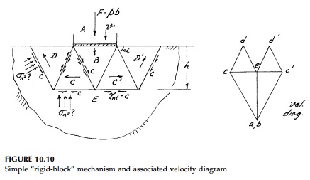
of each block is
represented by a single point. Thus the relative velocity between two
blocks is that vector joining the two corresponding points.
To construct the
diagram, one starts at point e as the zero reference since it represents
the stationary elastic portion of the structure. The velocity of the bearing
plate (indenter) is laid off to some arbitrary scale (since the magni-tude is
unknown). Blocks A and B move vertically the same amount (wedge B is an
extension of A) so a and b must coincide. Then C is known since
it must be horizontal to e, and at a given angle, to b. Similarly
d is located graphically from c and e and the points c' and d' from symmetry.
The
energy balance is therefore:
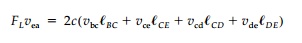
where
l
is the length of the interface and all energy terms are, of course, posi-tive.
Note also that the absolute size of the velocity diagram will have no effect on
the calculation. For the mechanism shown, made up of equilateral train gles,
all the lengths equal b and
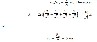
This is 9% less than
the simple slip circle mechanism (pL 6.29c) and it can
be reduced slightly by optimizing the size and shape of the triangles (see
P10.17). However, this is certainly not the correct family of slip surfaces and
thus, no matter how hard we might try to find the optimum layout of rigid
sliding blocks in this family of collapse modes, we shall never reach the
“exact” value of pL. As engineers we should not let this
bother us too much.
However, for EPS materials and in some cases for more difficult Mohr-Coulomb materials (cast iron, concrete, soil), it is possible to derive from the basic equilibrium equations and yield condition, the geometric characteris-tics of the correct family of ship surfaces. We may even be able to solve for the most critical one and the corresponding exact limit load. This is the topic explored in coming pages.
Related Topics