Chapter: Physics : Acoustics and Ultrasonics
Piezo Electric Crystals: Principle, Construction, working, Advantages and Disadvantages

Piezo Electric Crystals
The crystals which produce piezo-electric eect and converse Piezo electric effect are termed as Piezo electric crystal.
Example: Quartz, Tourmaline, Rochelle Salts etc.
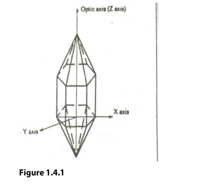
At typical example or a piezo electric crystal (Quartz) is as shown in the igure 1.4.1. It has an hexagonal shape with pyramids attached at both ends. It consists of 3 axes. Viz.,
(i) Optic Z axis, which joins the edges of the pyramid
(ii) Electrical axis(X axis), which joins the corners of the hexagon and
(iii) Mechanical axis, which joins the center or sides of the hexagon as shown


X-cut and Y cut crystals
X-Cut crystal:
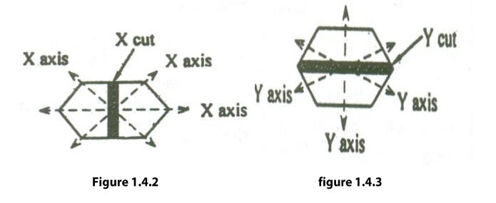
When the crystal is cut perpendicular to the X-axis, as shown in the figure 1.4.2, then it is called X-crystl.
Generally X-cut crystals are used to produce longitudinal ultrasonic waves.
Y-Cut Crystal:
When the crystal is cut perpendicular to the Y-axis, as shown in the figure 1.4.3, then it is called Y-cut crystal.
Generally, Y-Cut crystal produces transverse ultrasonic waves.
Piezoelectric Effect
Definition: When a mechanical stress is applied to the mechanical axis with respect to optical axis, a potential difference is developed across the electrical axis with respect to optic axis
Inverse Piezoelectric Effect:
Definition: When an alternating electric field is applied to electrical axis with respect to optical axis, expansion or contraction takes place in the mechanical axis with respect to optical axis.
Production of Ultra sonic waves –
Piezo Electric Effect
Principle:
This
is based on the Inverse piezoelectric
effect. When a quartz crystal is subjected to an alternating potential
difference along the electric axis, the crystal is set into elastic vibrations
along its mechanical axis. If the frequency of electric oscillations coincides
with the natural frequency of the crytal, the vibrations will be of large
amplitude. If the frequency of the electric field is in the ultrasonic
frequency range, the crystal produces ultrasonic waves.

Construction:
The
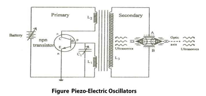
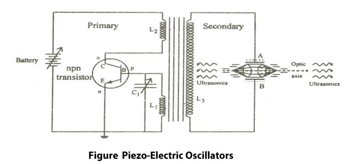
circuit diagram is shown in the figure 1.5 It is base turned oscillator
circuit. A slice of Quartz crystal is placed between the metal plates A and B
so as to form a parallel plate capacitor with the crystal as the dielectric.
This is coupled to the electronic oscillator through the primary coil L3
of the transformer.
Coils
L2 and L1 of oscillator circuit are taken for the primary
of the transformer. The collector coil L2 is inductively coupled to
base coil L1. The coil L1 and variable capacitor C form
the tank circuit of the oscillator.
Working:
When
the battery is switched on, the oscillator produces high frequency
oscillations. An oscillatory e.m.f is induced in the coil L3 due to transformer
action. So the crystal is now under high frequency alternating voltage.
The
capacitance of C1 is varied so that the frequency of oscillations produced is
in resonance with the natural frequency of the crystal. Now the crystal
vibrates with larger amplitude due to resonance. Thus high power ultrasonic
waves are produced.
Condition for Resonance:
Frequency
of the oscillator circuit = Frequency of the vibrating crystal

Where
‘l’ is the length o the rod
‘E’
is the Young’s modulus o the rod
‘ρ’
is the density of the material of the rod.
‘P’
= 1,2,3 …. Etc for fundamental, first overtone, second overtone etc
respectively
Advantages:
1.
Ultrasonic frequencies as high as 500MHz
can be generated.
2.
The output power is very high. It is not
affected by temperature humidity.
3.
It is more efficient than the
Magnetostriction oscillator.
4.
The breadth of the resonance curve is
very small. So we can get a stable and constant frequency of ultrasonic waves.
Disadvantages:
1.
The cost of the quartz crystal is very
high.
2. Cutting and shaping the crystal is quite
complex.
Related Topics