Chapter: Mechanical : Heat and Mass Transfer : Conduction
One Dimensional Steady State Heat conduction Composite Systems
ONE DIMENSIONAL STEADY STATE
HEATCONDUCTION COMPOSITE SYSTEMS:
Composite Surfaces
There are many
practical situations where different materials are placed m layers to form
composite surfaces, such as the wall of a building, cylindrical pipes or
spherical shells having different layers of insulation. Composite surfaces may
involve any number of series and parallel thermal circuits.
Heat Transfer Rate through a Composite
Wall
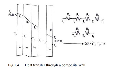
Let us consider a
general case of a composite wall as shown m Fig. 1.5 The different materials of
thicknesses L1, L2, etc and having thermal conductivities
kl, k2, etc. On one side of
the composite wall, there is a fluid A at
temperature TA and on the other side of the wall there is a fluid B
at temperature TB. The convective heat transfer coefficients on the
two sides of the wall are hA and hB respectively. The
system is analogous to a series of resistances as shown in the figure.

Fig
1.4 Heat transfer through a composite
wall
The Equivalent Thermal Conductivity
The process of heat transfer through compos lie and
plane walls can be more conveniently compared by introducing the concept of
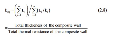
'equivalent thermal conductivity', keq. It is defined as:

And, its value
depends on the
thermal and physical
properties and the
thickness of each constituent of the composite structure.
An Expression for the Heat Transfer Rate
through a Composite Cylindrical System
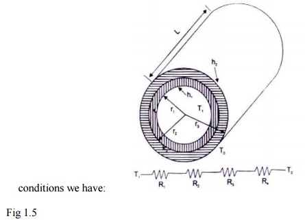
Let us consider a composite cylindrical system
consisting of two coaxial cylinders, radii r1, r2 and r2
and r3, thermal conductivities kl and k2 the
convective heat transfer coefficients at the inside andoutside surfaces h1
and h2 as shown in the figure. Assuming radial conduction under
steady state

conditions we have: Fig 1.5
R1
=1/ h1A1 =1/
2 1 pLh1
R2
=ln (r2
/ r1 )2 pLk1
R3
=ln (r3
/ r2 )2 pLk2

Related Topics