Chapter: Automation, Production Systems, and Computer Integrated Manufacturing : Numerical Control
Numerical Control(NC) Part Programming Using CAD/CAM
NC Part Programming Using CAD/CAM
A CAD/CAM system is a computer interactive
graphics system equipped with software is accomplish certain tasks in
design and manufacturing and to integrate the design and manufacturing
functions. We discuss ('AD/CAM in Chapter 24. One of the important tasks
performed on a CAD/CAM system is NC part programming. In this method of part
programming, portions of the procedure usually done by the part programmer are
instead done by the computer. Recall that the two main tasks of the part
programmer in computerassisted programming are (1) defining the part geometry
and (2) specifying the tool path. Advanced CAD/CAM systems automate portions of
both of these tasks.
Geometry
Definition Using CAD/CAM. A fundamental objective of CAD/CAM is to
integrate the design engineering and manufacturing engineering functions.
Certainly one of the important design functions is to design the individual
components of the product. If a CAD/e' AM system is used, a computer graphics
model of each part is developed by the designer and stored in the CAD/CAM data
base. That model contains all of the geometric, dimensional, and material
specificatluns for the part.
When the
same CAD/CAM system, or a CAM system that has access to the same CAD data base
in which the part model resides, is used to perform NC part programming, it
makes little sense to recreate the geometry of the part during the programming
procedure. Instead, the programmer has the capability to retrieve the part
geometry model from storage and to use that model to construct the appropriate
cutter path. The significant advantage of using CAD/CAM in this way is that it
eliminates one of the tirneconsurning steps in computerassisted part
programming: geometry definition. After the part geometry has been retrieved,
the usual procedure is to lahel the geometric elements that will be used during
part programming. These labels are the variable names (symbols) given to the
lines, circJe~ and surfaces that comprise the part. Most systems have the
capacity to automatically label the geometry clements of the part and to
display tbe labels on the monitor. The programmer can then refer to those
labeled elements during tool path construction.
If the NC
programmer does not have access tothe data base, then the geometry of the part
must be defined. This is done by using similar interactive graphics techniques
that the product designer would use to design the part. Points are defined in a
coordinate system using the computer graphics system, lines and circles are
defined from the points, surfaces are defined. and so forth, to construct a
geometric model of the part. The advantage of using the interactive graphics
system over conventional computerassisted part programming is that the
programmer receives immediate visual verification of the definitions being
created. This tends to improve the speed and accuracy of the geometry definition
process
Tool
Path Generation Using CAD/CAM. The second task of the NC
programmer in computerassisted part programming is tool path specification, The
first step in specifying the tool path is La select the cutting tool for the
operation. Most CADICAM systems have tool libraries that
can be called by the programmer to identify what tools arc available in the
tool crib. The programmer must decide which of the available tools is must
appropriate for the operation under consideration and specify it for the tool
path. This permits the tool diameter and other dimensions to be entered
automatically for tool offset calculations. If the desired cutting tool is not
available in the library, an appropriate tool can be specified by rhc
programmer. It then becomes part of the library for future use
The next
step is tool path definition. There are differences in capabilities of the
various CAD/CAM systems, which result in different approaches fur generating
the tool path. The most basic approach involves the use of the interactive
graphics system to enter the motion commands cnebyone.uirnilar to
computerassisted part programming. Individual statements in APT or other part
programming language are entered. and the CAD/CAM system provides an immediate
graphic display of the action resulting from the command. thereby validating
the statement.
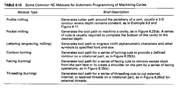
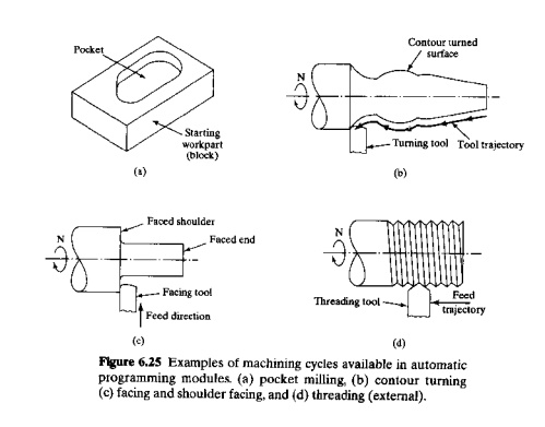
A
moreadvanced approach for generating tool path commands is to use one of the
automatic software modules available on the CAD/CAM system. These modules have
been developed to accomplish a number of common machining cycles for milling,
drilling, and turning. They are subroutines in the NC programming package that
can be called and the required parameters given to execute the machining cycle.
Several of these modules are identified in Table 6.13 and Figure 6.25.
When the
complete part program has been prepared, the CAD/CAM system can provide an
animated simulation of the program for validation purposes.
Computer Automated
Part Programming. In the CAD/CA M approach to NC part programming, several aspects of
the procedure are automated. In the future, it should be possible to automate
the complete NC part programming procedure. We are referring to this fully
automated procedure as computerautomated part programming. Given the geometric
model of a part that has been defined during product design, the
computerautomated system would possess sufficient logic and decisionmaking
capability to accomplish NC part programming for the entire part without human
assistance.
This can
most readily be done for certain NC processes that involve welldefined,
relatively simple part geometries. Examples are pointtopoint operations such as
NC drilling and electronic component assembly machines. In these processes, the
program conststs basically of a series of locations in an xy
coordinate system where work is to be performed [e.g .. holes arc to be drilled
or components are to be inserted). These locations are determined by data that
are generated during product design. Special algorithms can be developed to
process the design data and generate the NC program fur the particular system. "fe contounag
systems will eventually be capable at a similar level of automation. Automatic
programming of this type is closely related to computer-automated process
planning (CAPP), discussed in later pages.
Related Topics